Compression device

a compression device and a technology for limbs, applied in the field of tourniquets, can solve the problems of inability to apply on entrapped or severely mangled limbs, difficult and slow application of tourniquets, and inability to self-apply, etc., and achieve the effects of easy portability, quick deployment, and minimal nois

Active Publication Date: 2016-12-01
SWIFT STRAP
View PDF2 Cites 18 Cited by
  • Summary
  • Abstract
  • Description
  • Claims
  • Application Information

AI Technical Summary

Benefits of technology

[0019]Embodiments of the present invention have many advantages. The compression device and method are useful for applying pressure on a limb in a manner suitable for the occlusion of blood flow. The device can be used as a tourniquet in military and civilian settings. The tourniquet can be applied with one hand and around objects or limbs with no accessible open end. Additionally, the tourniquet does not normally slip or rotate during application and it does not pinch skin or other loose objects or surfaces during application. Minimal noise is made during the application and tightening of the device. The device is lightweight and compact so as to be easy to carry and quick to deploy.

Problems solved by technology

Many tourniquets have been made as devices that require two hands to effectively apply them, making them inappropriate for self-application.
This proves to be a hindrance in the cinching process, making the application of the tourniquet difficult and slow.
These tourniquets are in the form of closed loops and can only be slid on from an open end, making them impossible to apply on entrapped or severely mangled limbs.
However, accidental opening of the loop after application is a concern with these tourniquets.
However, pulling on the outer loop also creates friction between the loops, preventing the mechanism from effectively working
However, this structure limits application to only limbs of certain sizes.
It also adds bulk to the device making it difficult to carry.
In addition, it has a tendency to severely pinch skin when applied.
This can cause excessive pain and discomfort and prevent a user from adequately tightening the device, making it ineffective.
Sound is particularly undesirable in military applications in hostile combat zones where it may expose the user's position.

Method used


Image

  • Compression device
  • Compression device
  • Compression device

Examples


Embodiment Construction

[0043]A description of example embodiments of the invention follows.

[0044]The teachings of all patents, published applications and references cited herein are incorporated by reference in their entirety.

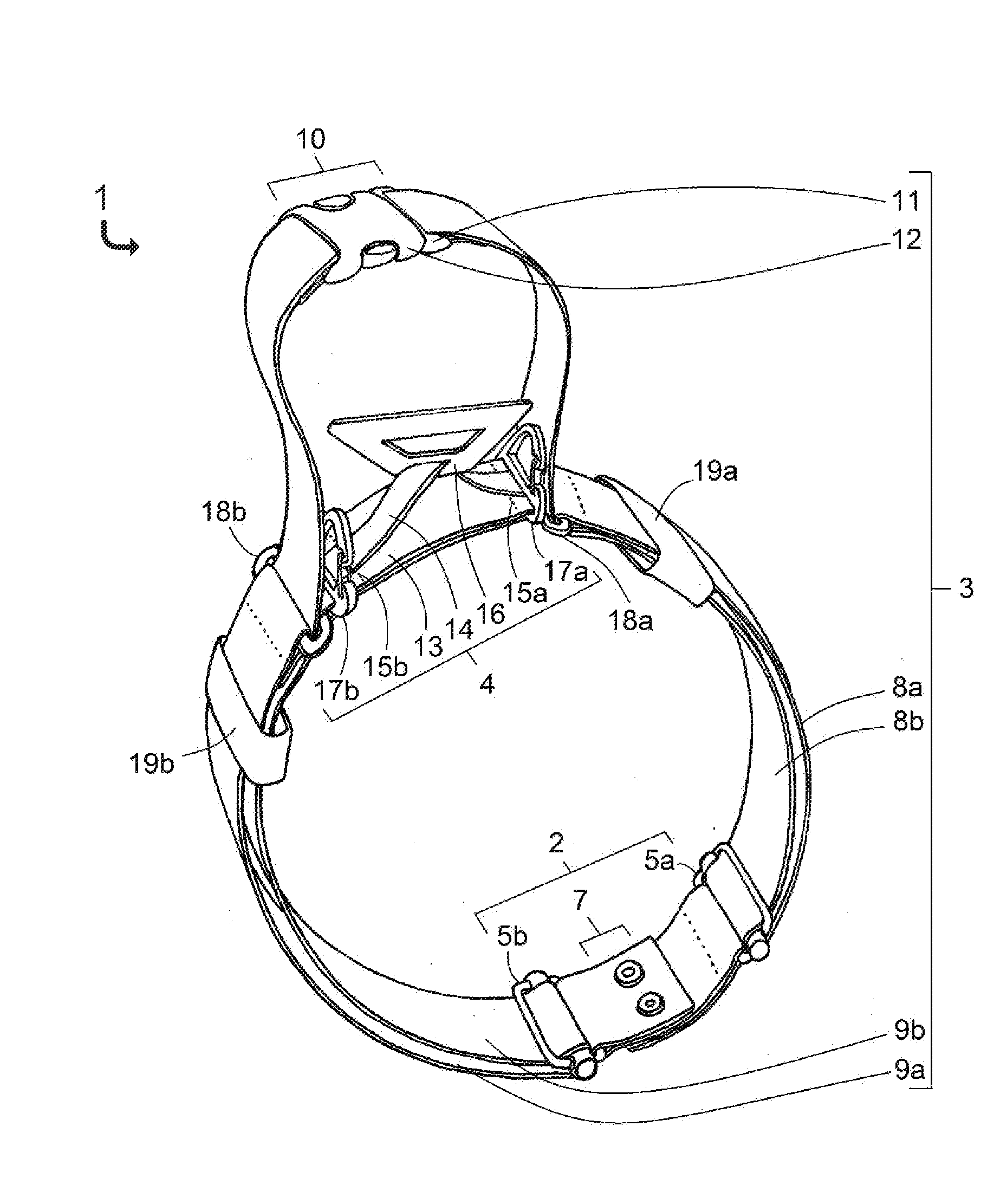
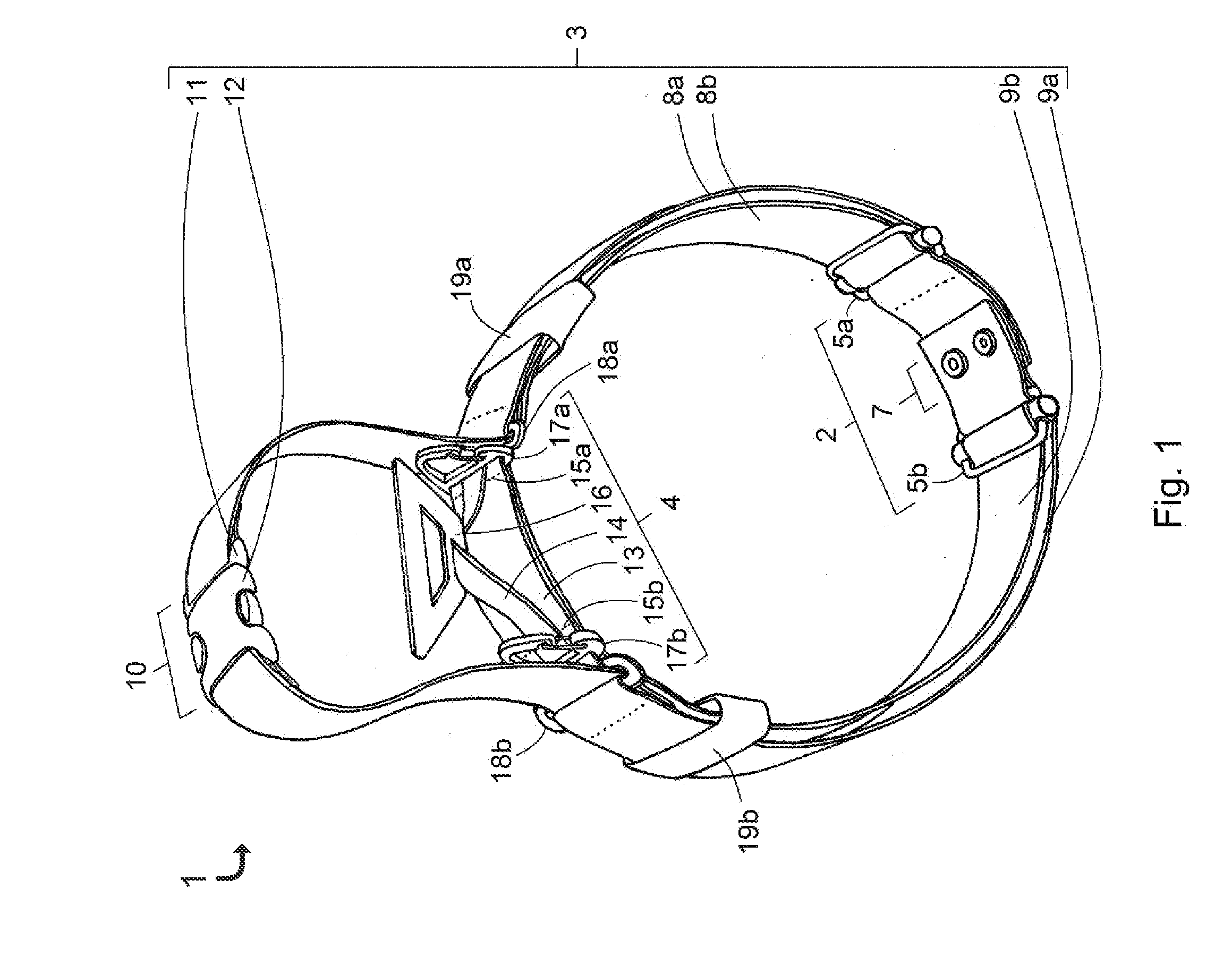
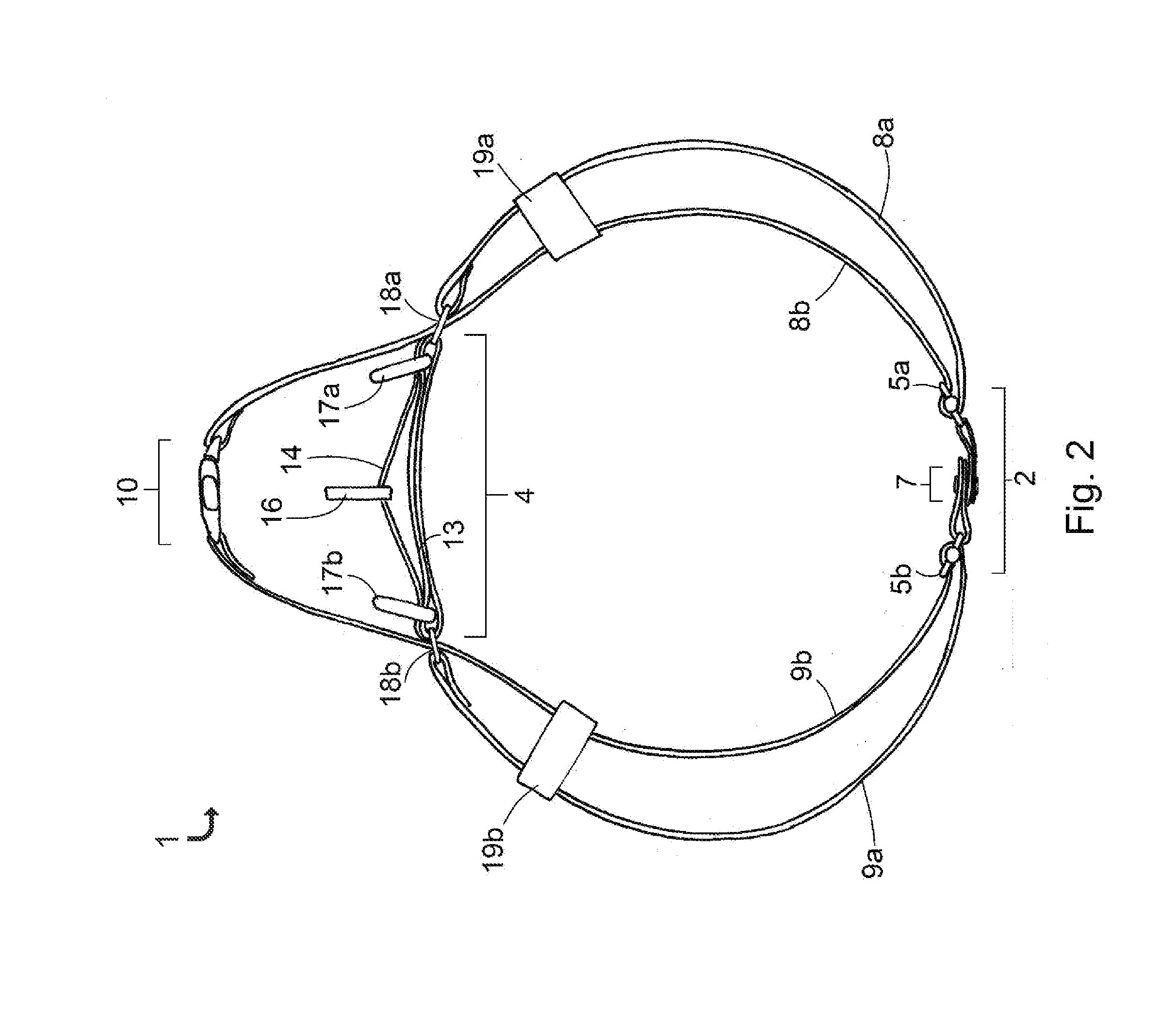
[0045]Referring to FIGS. 1-2, a compression device 1 according to an embodiment of the present invention is shown. The compression device 1, as shown, is a tourniquet. The device includes a first buckle assembly 2, a cinch member (strap) 3, and a tightening mechanism 4. The first buckle assembly 2 includes sliding buckles 5a and 5b, both of which have sliding bars 6a and 6b designed to accomplish a single-direction locking action further described with reference to FIGS. 10-13. The first buckle assembly 2 can be joined / separated using the popper assembly 7. The cinch member 3 comprises a first flexible elongated member, including outer segment 8a and inner segment 8b, outer segment 9a and inner segment 9b, and an optional second buckle assembly 10. The second buckle assembly 10 inclu...


PUM


Abstract

A compression device, useful for applying circumferential compression to an object, for example, as a tourniquet to occlude blood flow in a hemorrhaging extremity, is provided. The device includes a buckle assembly, first and second guidance slides, a connecting member between the first and second guidance slides, and a strap. Each end of the strap is anchored to a guidance slide. From each of the anchored ends, the strap passes through the buckle assembly, forming outer segments. The strap then returns along respective insides of the outer segments and through the guidance slides, forming inner segments. The buckle assembly, inner segments and connecting member form a loop for placing about an object, an inner circumference of the loop being adjustable by pulling on a portion of the strap located along the outside of the connecting member and between the two guidance slides to tighten the loop around the object.

Description

RELATED APPLICATIONS[0001]This application claims the benefit of U.S. Provisional Application Nos. 61 / 935,391, filed on Feb. 4, 2014, and 61 / 992,895, filed on May 14, 2014. The entire teachings of the above applications are incorporated herein by reference.GOVERNMENT SUPPORT[0002]This invention was made with government support under W81XWH-09-2-001 from USAMRMC. The government has certain rights in the invention.BACKGROUND OF THE INVENTION[0003]There are several tourniquets on the market that can be used, in cases of severe limb hemorrhage, by cinching to remove slack from the tourniquet and then tightening it to apply pressure to the limb. Many tourniquets have been made as devices that require two hands to effectively apply them, making them inappropriate for self-application. A few tourniquets that are applicable with just one hand, of the type described in U.S. Pat. No. 7,892,253 and U.S. Pat. No. 7,776,064, require pulling on webbing in a direction tangential to the limb for ci...

Claims


Application Information

Patent Timeline
Patent Type & Authority Applications(United States)
IPC IPC(8): A61B17/132
CPCA61B17/1327A61B17/1322
Inventor DEMAS, NICKOLAS PETERHUNT, ANTON STUARTHAMER, TYLER T.ZAYYAD, ZAIDCONNOR, JAMES F.GUERRERO, JULIO C.JAIN, PRANNAY
Owner SWIFT STRAP
Why Eureka
Try Eureka