
Frontal illumination of a surface using LED lighting

a technology of led lighting and frontal illumination, applied in the field of billboard lighting, can solve the problems of increased maintenance costs, increased physical structures, and increased wind load, and achieve the effects of reducing maintenance costs, increasing maintenance costs, and increasing costs

Active Publication Date: 2011-03-01
FORMETCO LLC
View PDF10 Cites 45 Cited by
  • Summary
  • Abstract
  • Description
  • Claims
  • Application Information

AI Technical Summary

Benefits of technology

"The present invention relates to a new method of lighting billboards and buildings using LED lights. The invention solves problems associated with current lighting methods, such as the need for a large number of light sources to provide even illumination and the use of wide-angle light sources which cause energy waste and light pollution. The invention provides a new LED lamp array that can be used to create a more even and visually appealing illumination of the billboard surface. The LED lamp array is designed to be mounted on the billboard support structure, and can be positioned to illuminate the copy area without causing noticeable differences in brightness between different areas. The invention is a more efficient, cost-effective, and aesthetically pleasing solution for lighting billboards and buildings."

Problems solved by technology

Typically, because of the beamwidth limitations of the light source, two or more light fixtures are needed to illuminate the copy area.
A larger number of light sources provides for more even illumination of the copy area, but generally results in higher costs, more physical structures, higher wind loading, and more maintenance issues.
Conversely, a lower number of light sources results in lower cost, fewer physical structures, lower wind loading, and fewer maintenance issues, but increases the likelihood that there will be noticeable and undesirable differences between better lit (lighter) areas and more poorly lit (darker) areas.
The use of wide angle light sources, however, brings on other problems such as, but not limited to, (1) inefficiency because the use of wide-angle light sources causes a substantial amount of the light emitted to be spread outside the borders of the copy area; (2) undesired heat generation because more light output, and therefore more energy, is required so that the light which strikes the copy area is of sufficient intensity to properly illuminate the copy area; and (3) light pollution problems because the light which does not strike the copy area contributes to night sky light pollution.
Night sky pollution has become such a severe problem in many large cities that only the brightest stars are visible at night.
Simply replacing the current light sources with LED light sources would seem to be a solution but, in reality, is not a solution because of several problems: (1) a large number of LEDs is required to provide the desired illumination, (2) the optics and lensing required to illuminate the copy area sufficiently is very complex, (3) the heat generated by a large number of LEDs in close proximity or clustered together causes the LEDs to quickly overheat and fail, and (4) cost, windloading, esthetic, maintenance, and other considerations.

Method used


Image

  • Frontal illumination of a surface using LED lighting
  • Frontal illumination of a surface using LED lighting
  • Frontal illumination of a surface using LED lighting

Examples


Embodiment Construction

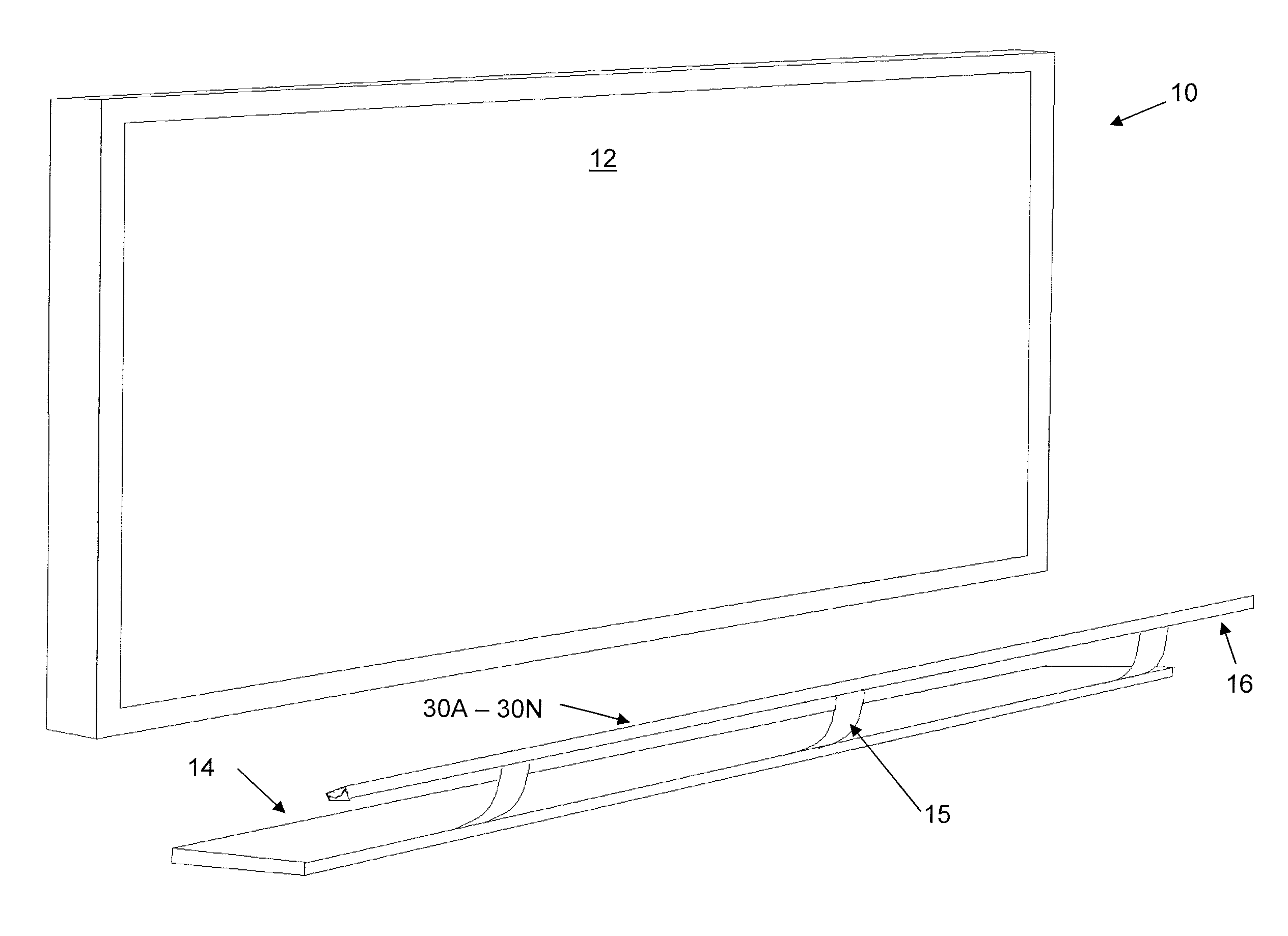
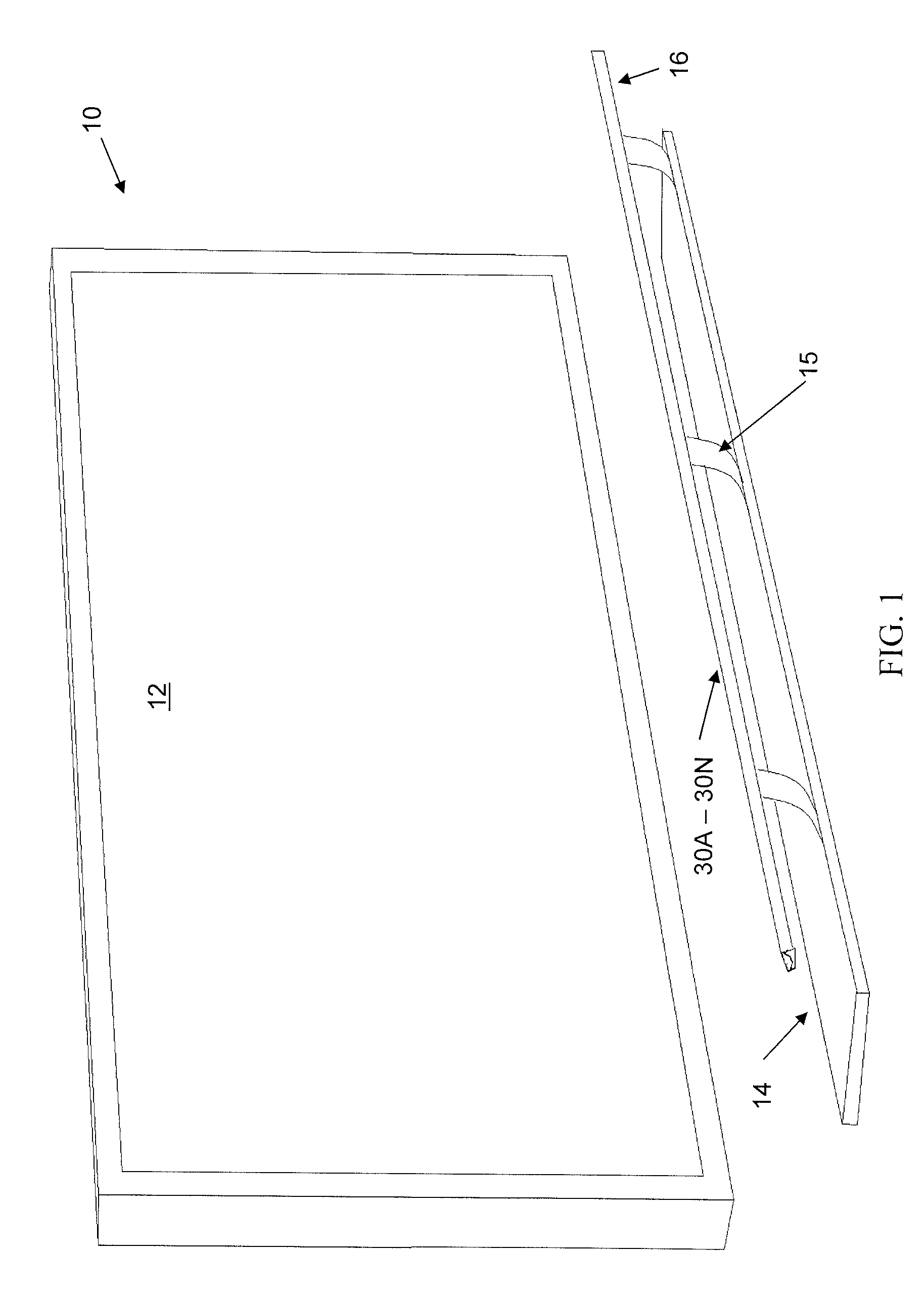
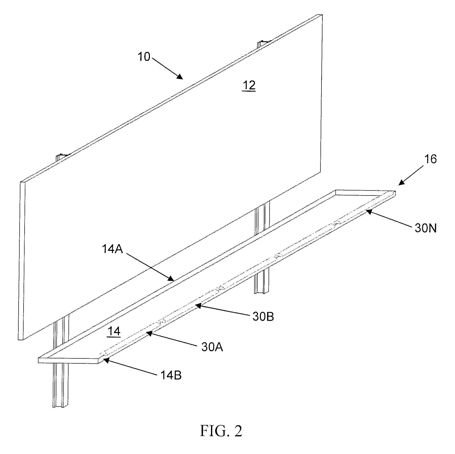
[0019]FIGS. 1-3 illustrate embodiments of various billboard installations and some location possibilities for LED lamp arrays. FIG. 1 is an illustration of one embodiment of a billboard 10 and shows the billboard face 12, the catwalk 14, and one possible location 16 for lamp arrays 30A-30N. FIG. 2 is an illustration another embodiment of a billboard 10, and shows the billboard face 12, the catwalk 14, and another possible location 16 for the lamp arrays 30. FIG. 3 is an illustration of another embodiment of a billboard 10 and shows the billboard face 12, the catwalk 14, another possible location 16 for the lamp arrays 30, and the preferred light dispersion characteristic 20.

[0020]The front illuminated sign has a plurality of LED lamp arrays 30A-30N, also referred to herein as light fixtures, preferably mounted to the service access catwalk 14 kickrail, and parallel to the advertising sign face 12. An adjustable mounting bracket 15 accommodates various relationships between the adver...


PUM


Abstract

A plurality of lamp arrays (30A-30N) provide uniform lighting across the copy area of a billboard sign. The arrays (30) are arranged end-to-end horizontally along the length of the copy area. Each array (30) comprises a plurality of LEDs (34A-34N) and a plurality of lenses (36A-36M). The various lenses (36) direct and focus the light from the LEDs (34) at the various parts of the copy area so as to minimize dark and light spots. A “TOP” set of LEDs preferably illuminates the top part of the copy area, a “MIDDLE” set of LEDs preferably illuminates the middle of the copy area, and “FILLER” LEDs preferably serve to illuminate the bottom of the copy area. The lamp arrays are preferably mounted to a catwalk (14) at the bottom of the billboard.

Description

PRIORITY CLAIM[0001]This application claims the priority of U.S. Provisional Patent Application 61 / 029,952 filed on Feb. 20, 2008, entitled “Frontal Illumination Of A Surface Using Led Lighting” by Todd R. Heller and Dewey T. Pitts. The entirety of the above provisional application is hereby incorporated herein by reference.BACKGROUND OF THE INVENTION[0002]1. Field of the Invention[0003]The present invention generally relates to lighting of billboards, signs, buildings, and other structures and, more particularly, relates to front illumination of surfaces using light emitting diodes (LEDs).[0004]2. Description of the Related Art[0005]Historically, light fixtures providing front illumination of large advertising billboards have utilized various types of illumination sources, including electro-florescent tubes and flood lights (incandescent, high energy discharge, projection lamps). The illumination source is enclosed in a fixture which is mounted on an extended arm, and the extended ...

Claims


Application Information

Patent Timeline
Patent Type & Authority Patents(United States)
IPC IPC(8): G09F13/02
CPCG09F13/02G09F2013/222Y10S362/812
Inventor HELLER, TODD R.PITTS, DEWEY T.
Owner FORMETCO LLC
Learn More