
Inversion table

a technology of inversion table and backrest, which is applied in the field of inversion table, can solve the problems of difficult and laborious rotation of the backrest, and achieve the effect of convenient operation

Inactive Publication Date: 2011-03-01
PARADIGM HEALTH & WELLNESS
View PDF17 Cites 2 Cited by
  • Summary
  • Abstract
  • Description
  • Claims
  • Application Information

AI Technical Summary

Benefits of technology

[0007]The main objective of the present invention is to provide an inversion table that can be operated easily.
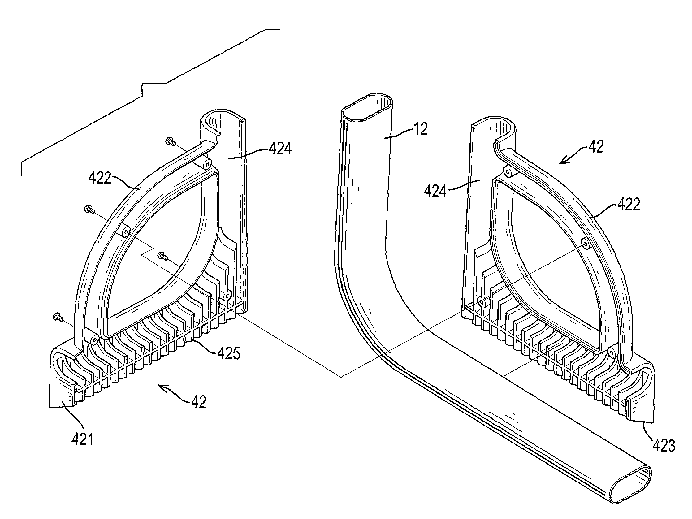
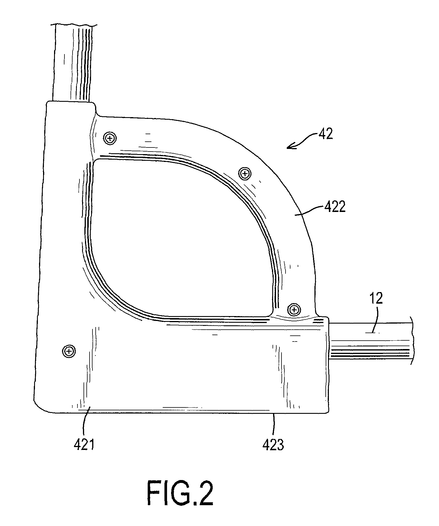
[0008]The inversion table in accordance with the present invention has a mounting bracket, a backrest, an ankle clamp assembly and a holding device. The mounting bracket has a rear supporting frame and two front supporting legs to form a triangular form. The backrest is connected pivotally to the rear supporting frame. The ankle clamp assembly is securely connected to the backrest to clamp and hold a person's ankles. The holding device is mounted on the rear supporting frame of the mounting bracket at a position opposite to the ankle clamp assembly and has two holding bars. Each holding bar has two self-casings connected to each other around the rear supporting frame, and each self-casing has a mounting segment and a holding segment. The mounting segment is mounted on the rear supporting frame and has a mounting recess and multiple supporting ribs. The holding segment is formed on the free ends of the mounting segment to provide a holding and gripping effect.

Problems solved by technology

This is inconvenient.
Furthermore, when the person wants to rotate the backrest to return upright, the person has to hold the side bars of the mounting bracket to obtain an upward reverse force to rotate the backrest, but this is difficult and laborious to make the backrest rotate upright.

Method used


Image

  • Inversion table
  • Inversion table
  • Inversion table

Examples


Embodiment Construction

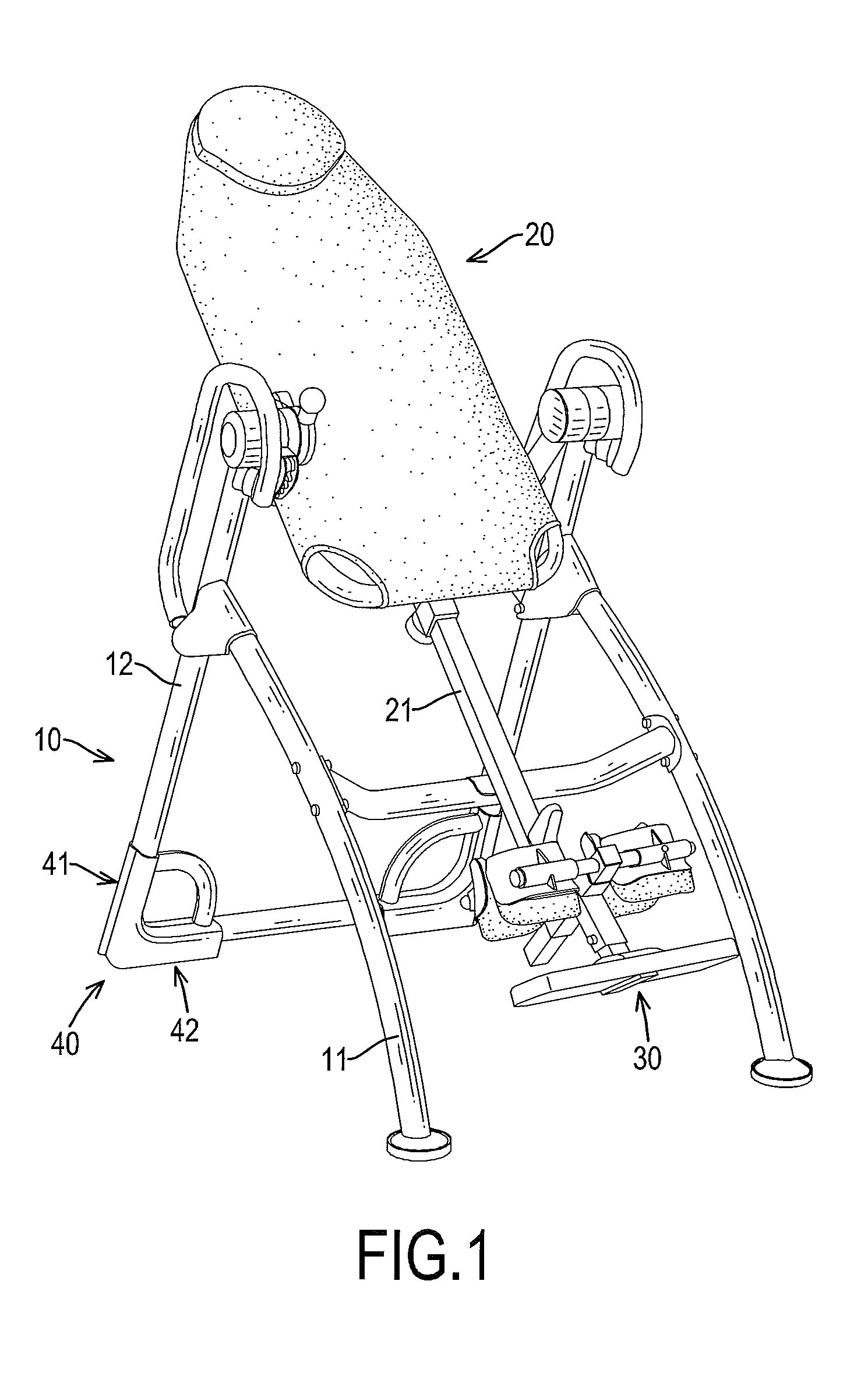
[0015]With reference to FIG. 1, an inversion table in accordance with the present invention has a mounting bracket (10), a backrest (20), an ankle clamp assembly (30) and a holding device (40).

[0016]The mounting bracket (10) has a rear supporting frame (12) and two front supporting legs (11) to form a triangle. The rear supporting frame (12) is U-shaped and has a bottom side, two free ends and two pivotal elements. Preferably, with reference to FIG. 3, the cross section of the bottom side of the rear supporting frame (12) is elliptical. The pivotal elements are separately mounted on the free end of rear supporting frame (12) and face each other. The front supporting legs (11) are respectively and securely attached to the rear supporting frame (12) near the free ends.

[0017]The backrest (20) is connected pivotally to the pivotal elements of the rear supporting frame (12) of the mounting bracket (10) and has a bottom end and a connecting arm (21). The connecting arm (21) is adjustably ...


PUM


Abstract

An inversion table has a mounting bracket, a backrest, an ankle clamp assembly and a holding device. The mounting bracket has a rear supporting frame and two front supporting legs. The backrest is connected pivotally to the rear supporting frame. The ankle clamp assembly is securely connected to the backrest to clamp a person's ankles. The holding device is mounted on the rear supporting frame of the mounting bracket at a position opposite to the ankle clamp assembly and has two holding bars. Each holding bar has two self-casings connected to each other around the rear supporting frame and each self-casing has a mounting segment and a holding segment. The mounting segment is mounted on the rear supporting frame and has a mounting recess and multiple supporting ribs. The holding segment is formed on the free ends of the mounting segment to provide a holding and gripping effect.

Description

BACKGROUND OF THE INVENTION[0001]1. Field of the Invention[0002]The present invention relates to an inversion table and, more particularly, to an inversion table that can be operated easily.[0003]2. Description of Related Art[0004]Conventional exercising machines include exercising bikes, treadmills and surfing machines. The conventional exercising machines have mechanical structures and linkage shafts to simulate exercise dynamics to exercise at least one muscle group for training, rehabilitation or the like. To use a conventional inversion table, a person lies on a backrest thereof to relax or relieve back pain. The conventional inversion backrest has a mounting bracket, a backrest and an ankle clamp assembly. The backrest is pivotally attached to the mounting bracket. The ankle clamp assembly is connected to the backrest to clamp and hold a person's ankles when the backrest is pivoted to an inverted position.[0005]When a person uses the conventional inversion table to invert, the...

Claims


Application Information

Patent Timeline
Patent Type & Authority Patents(United States)
IPC IPC(8): A63B26/00
CPCA61H1/0218A61H2201/1642A61H2203/0493
Inventor WEI, TSAO-KUANG
Owner PARADIGM HEALTH & WELLNESS
Learn More