
Apparatuses and methods to connect power sources to an electric power system

a technology of power source and electric power system, applied in emergency protective devices, relays, transportation and packaging, etc., can solve the problems of not being able to pass the full testing suite required to obtain regulatory approval, unable to implement, and unable to pass the full testing sui

Active Publication Date: 2011-03-01
NEWLIGHT CAPITAL LLC
View PDF45 Cites 117 Cited by
  • Summary
  • Abstract
  • Description
  • Claims
  • Application Information

AI Technical Summary

Benefits of technology

"The patent describes an apparatus and method for controlling distributed energy sources in a way that ensures they are compliant with standard requirements for interconnecting with electric power systems. The apparatus includes a controller with a sensor and a switch to selectively connect or disconnect an electric path between the energy source and the electric power system. The controller uses the sensor to monitor the output of the energy source and the switch to disconnect the energy source if it is not in compliance. The method includes monitoring the output of the energy source, determining if it is within a predetermined range, and controlling the switch accordingly. The apparatus and method can be used with different types of distributed energy sources and can be reconfigurable for different requirements. The technical effect is to ensure the safe and reliable connection of distributed energy sources to electric power systems."

Problems solved by technology

One of the factors contributing to the expense of such a system is associated with hooking up the distributed electrical generation system to the electricity grid, which has many requirements, such as those specified in the IEEE standard 1547 or other, similar standards in effect in Europe and other areas of the world for interconnecting distributed resources with electric power systems.
Although a distributed electrical generation system may be relatively easily designed to meet such requirements, it is rather expensive to pass the full testing suite required to obtain regulatory approval.
As a result, novel designs may be delayed, or not implemented at all, because the volume of a small series does not justify the expense of undergoing the approval process, which, in some cases, may cost US$100,000 or more.
In other cases, distributed electrical generation systems may be connected to the grid without obtaining regulatory approval, sometimes with disastrous consequences.

Method used


Image

  • Apparatuses and methods to connect power sources to an electric power system
  • Apparatuses and methods to connect power sources to an electric power system
  • Apparatuses and methods to connect power sources to an electric power system

Examples


Embodiment Construction

The following description and drawings are illustrative and are not to be construed as limiting. Numerous specific details are described to provide a thorough understanding. However, in certain instances, well known or conventional details are not described in order to avoid obscuring the description. References to one or an embodiment in the present disclosure are not necessarily references to the same embodiment; and, such references mean at least one.

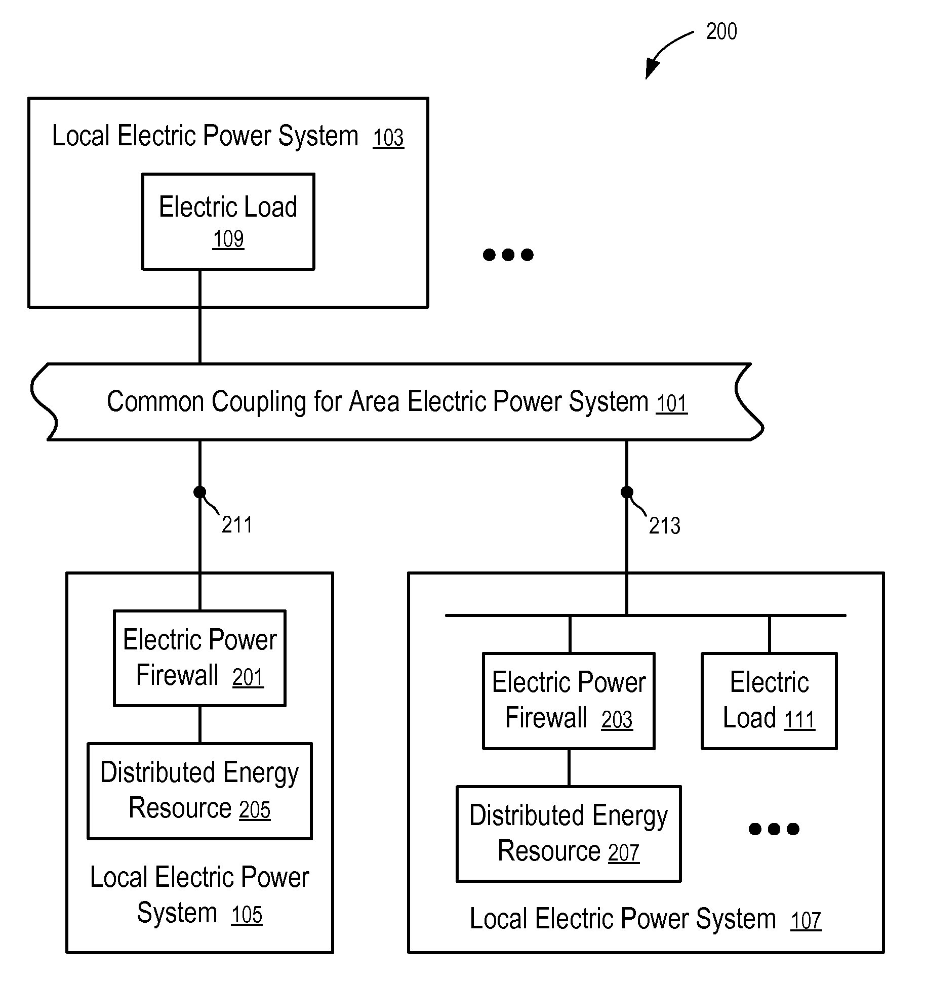
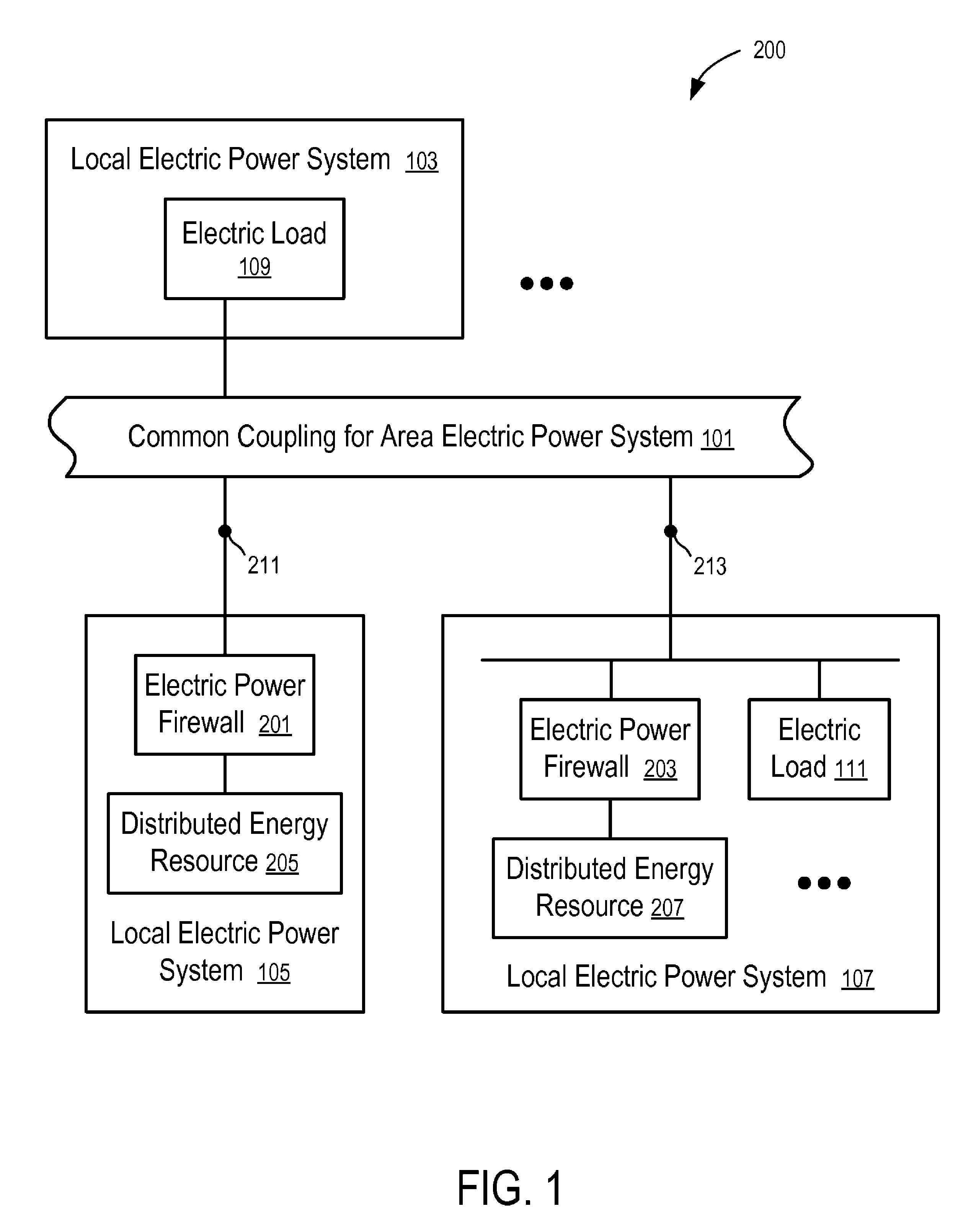
One embodiment of the disclosure provides methods and apparatuses of supervisory firewall for distributed electrical generation systems. The firewall can be inserted between a distributed energy resource and the electrical power system in such a way that the power generation system as connected via the firewall is in full compliance with regulations and, at the same time, does not require the expensive testing of the actual distributed energy resource.

FIG. 1 illustrates ways to connect distributed energy sources via electric power fi...


PUM


Abstract

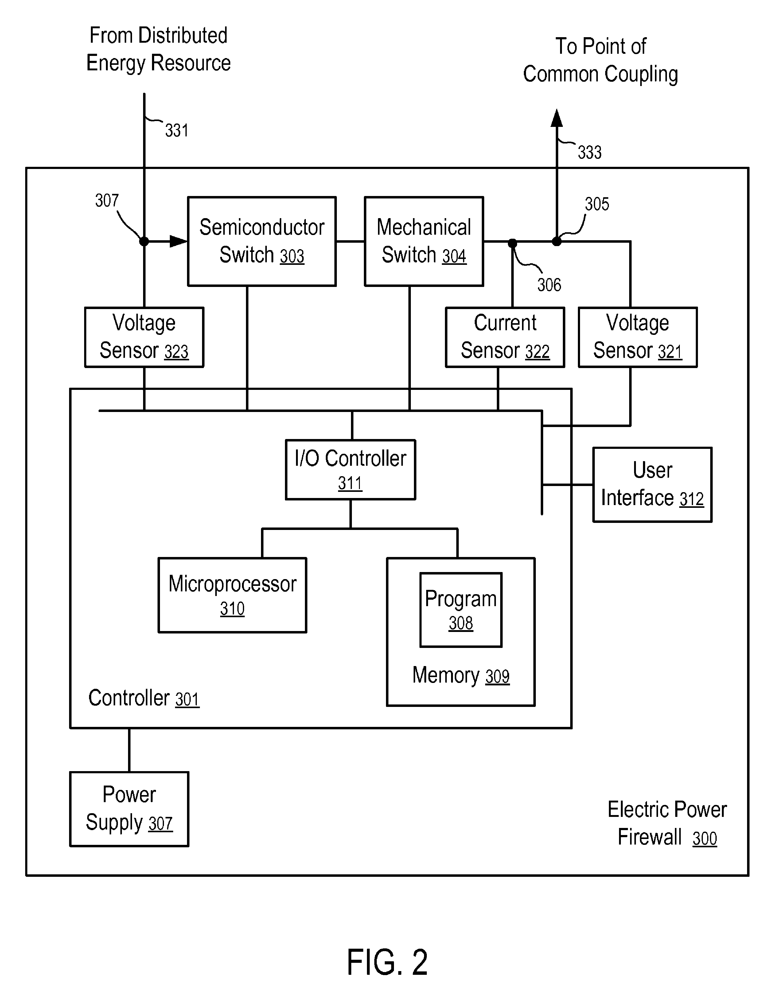
Apparatuses and methods to firewall distributed energy sources. In one aspect, an apparatus includes: a first connector configured to interface with a distributed energy source; a second connector configured to interface with a connection point of an electric power system; at least one switch coupled between the first connector and the second connector; at least one sensor coupled with the switch; and a controller coupled with the at least one switch, the controller to use the at least one switch to selectively connect or disconnect an electric path between the first connector and the second connector based on signals from the at least one sensor.

Description

FIELD OF THE TECHNOLOGYAt least some embodiments disclosed herein relate to connecting electric power generators to an electric power system in general and more particularly but not limited to, connecting distributed energy sources to an area electric power system.BACKGROUNDIndividuals and enterprises are currently employing distributed electrical generation systems with increasing frequency. A distributed electrical generation system may also be called a distributed energy resource, or distributed generator, or distributed resource.A distributed electrical generation system may be an electric generation facility connected to an Area Electric Power System (Area EPS). A distributed electrical generation system may be a small-scale electric generator located next to and connected to the load being served either with or without an electric grid interconnection. A distributed electrical generation system may use an advanced turbine, a reciprocating engine, a fuel cell, a photovoltaic pa...

Claims


Application Information

Patent Timeline
Patent Type & Authority Patents(United States)
IPC IPC(8): H02J1/00H02J3/00
CPCH02J3/42
Inventor POWELL, EARL G.HADAR, RON
Owner NEWLIGHT CAPITAL LLC
Learn More