Methods and systems for forming a protected disconnectable joint assembly

a technology of disconnectable joints and protective covers, which is applied in the direction of one-pole connections, dustproof/splashproof/drip-proof/waterproof/flameproof connections, coupling device connections, etc., can solve the problems of loss of seal with the cable adapter, long and bulky joint sleeve assembly, and difficulty in pushing cable adapters

Inactive Publication Date: 2011-03-08
TE CONNECTIVITY CORP
View PDF41 Cites 60 Cited by
  • Summary
  • Abstract
  • Description
  • Claims
  • Application Information

AI Technical Summary

Benefits of technology

[0006]According to method embodiments of the present invention, a method for forming a protected disconnectable joint assembly includes providing a disconnectable joint assembly. The disconnectable joint assembly includes: an electrical transmission power cable including a conductor and a cable insulation layer covering the conductor, the conductor having a terminal end; an electrically conductive cable connector affixed to the terminal end of the power cable and having a connector coupling portion; a busbar including an electrically conductive busbar body, a busbar coupling portion extending from the busbar body, and a busbar insulation layer covering the busbar body; and a disconnectable coupling mechanism mechanically securing the cable coupling portion to the busbar coupling portion to provide a joint between the cable and the busbar. The disconnectable coupling mechanism is sele...

Problems solved by technology

The cable adapters may be difficult to push on and may require holding collars to prevent them from sliding out of position when the joint sleeve is pushed over them.
The completed joint sleeve assembly may be long an...

Method used


Image

  • Methods and systems for forming a protected disconnectable joint assembly
  • Methods and systems for forming a protected disconnectable joint assembly
  • Methods and systems for forming a protected disconnectable joint assembly

Examples


Embodiment Construction

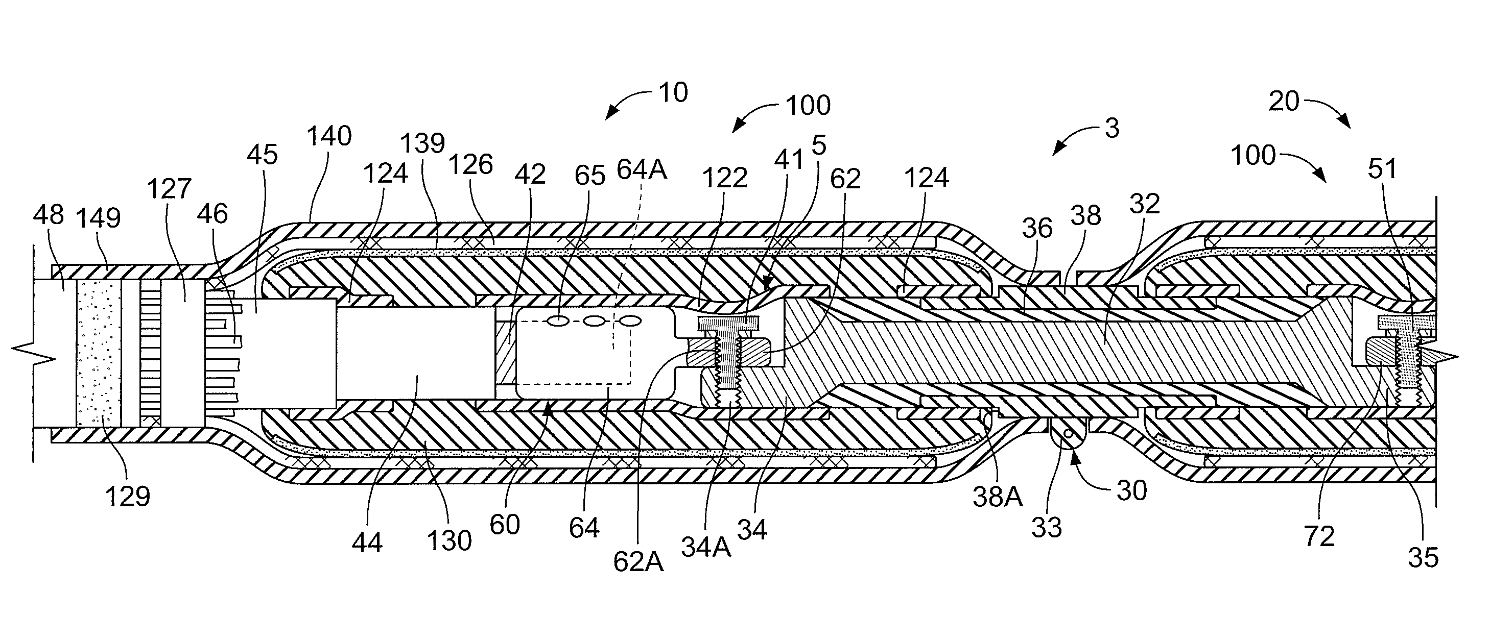
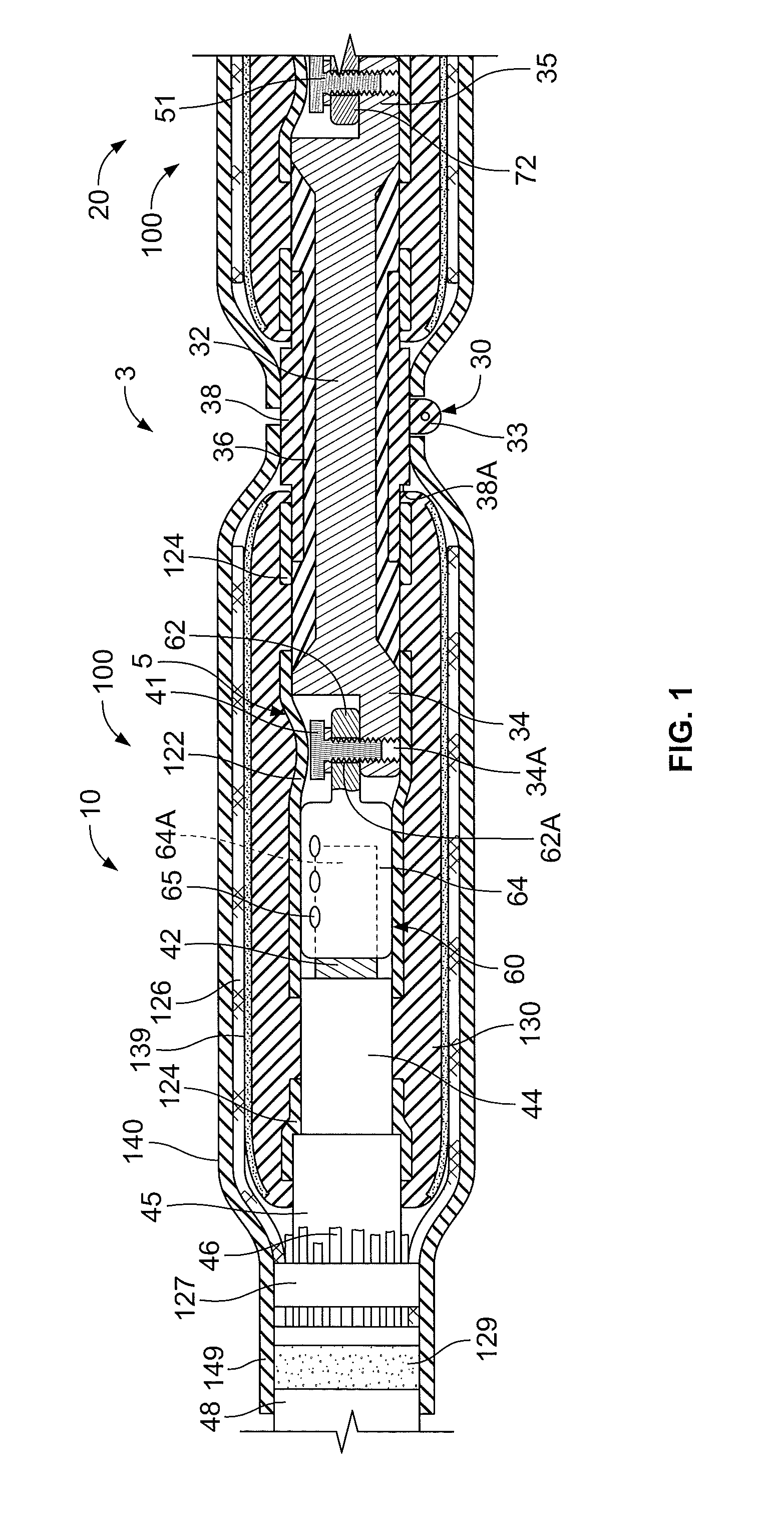
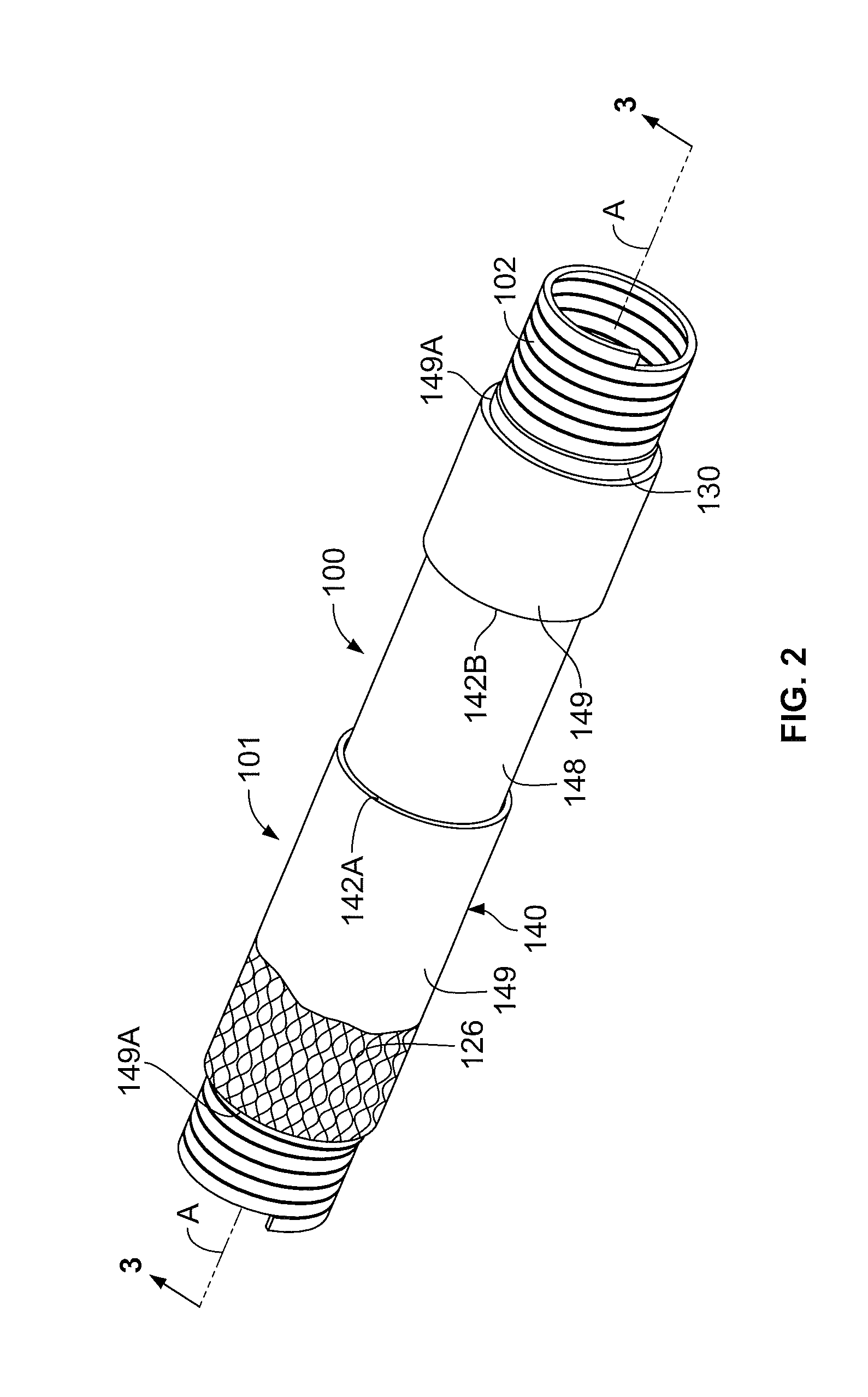
[0018]The present invention now will be described more fully hereinafter with reference to the accompanying drawings, in which illustrative embodiments of the invention are shown. In the drawings, the relative sizes of regions or features may be exaggerated for clarity. This invention may, however, be embodied in many different forms and should not be construed as limited to the embodiments set forth herein; rather, these embodiments are provided so that this disclosure will be thorough and complete, and will fully convey the scope of the invention to those skilled in the art.

[0019]It will be understood that when an element is referred to as being “coupled” or “connected” to another element, it can be directly coupled or connected to the other element or intervening elements may also be present. In contrast, when an element is referred to as being “directly coupled” or “directly connected” to another element, there are no intervening elements present. Like numbers refer to like elem...


PUM


Abstract

A method for forming a protected disconnectable joint assembly includes providing a disconnectable joint assembly. The disconnectable joint assembly includes: an electrical transmission power cable including a conductor and a cable insulation layer covering the conductor, the conductor having a terminal end; an electrically conductive cable connector affixed to the terminal end of the power cable and having a connector coupling portion; a busbar including an electrically conductive busbar body, a busbar coupling portion extending from the busbar body, and a busbar insulation layer covering the busbar body; and a disconnectable coupling mechanism mechanically securing the cable coupling portion to the busbar coupling portion to provide a joint between the cable and the busbar. The disconnectable coupling mechanism is selectively operable to disconnect the cable connector from the busbar without severing the cable. The method further includes: providing a joint cover assembly including a tubular, elastomeric cold-shrinkable sleeve body; maintaining the joint cover assembly in an expanded state using a removable holdout device mounted within the sleeve body; mounting the joint cover assembly on the holdout over the joint between the cable and the busbar; and thereafter removing the holdout device from the joint cover assembly to release the sleeve body to contract onto the disconnectable joint assembly such that the sleeve body circumferentially surrounds the joint between the cable and the busbar, overlaps portions of the cable insulation layer and the busbar insulation layer adjacent the joint, and applies a persistent radially compressive load on the cable insulation layer and the busbar insulation layer.

Description

FIELD OF THE INVENTION[0001]The present invention relates to electrical cables and connections and, more particularly, to protective covers for disconnectable joints.BACKGROUND OF THE INVENTION[0002]Disconnectable joint busbars are commonly used in electrical power transmission networks in urban environments. The busbar includes a body with two or more posts or lugs extending therefrom and an electrical insulation layer covering the body. Electrical power cables to be spliced are provided with a cable termination lug or connector. Each cable termination lug is disconnectably and reconnectably secured to a respective busbar lug by a bolt or the like, for example.[0003]Disconnectable joint assemblies as described above are useful in urban network applications where a utility may need the ability to disconnect a joint to sectionalize a piece of cable for repair, for example. By way of example, a bad or damaged cable may be disconnected from the busbar to remove the cable from the circu...

Claims


Application Information

Patent Timeline
IPC IPC(8): H01R13/52
CPCH01R4/34H01R4/72H01R43/005H02G5/007H02G15/1833H01R2101/00
Inventor YAWORSKI, HARRY GEORGE
Owner TE CONNECTIVITY CORP
Why Eureka
Try Eureka