Hybrid metal-plastic roof vent

a technology of metal-plastic roof vents and roof vents, which is applied in the field of roof vents, can solve the problems of roof vent cover being continually exposed to the elements, deteriorating faster than the rest of the vent, and being expensive and susceptible to rust, denting,

Active Publication Date: 2011-03-08
OHAGIN CAROLINA STOLLENWERK
View PDF22 Cites 66 Cited by
  • Summary
  • Abstract
  • Description
  • Claims
  • Application Information

AI Technical Summary

Benefits of technology

[0011]In accordance with another aspect, a vent for a roof is provided comprising a first member adapted to be positioned within and exposed at an upper surface of a roof; a second member configured to attach to and be positioned below and spaced apart from the first member to define a ventilation gap therebetween and having at least one opening; and an air-conveying connector configured to attach to an underside of the second member and in fluid communication with the opening. The at least one opening is covered by the first member when the first and second members are attached to substantially prevent rain from entering the opening. The ventilation gap is in fluid communication with an area above the first member when the first and second members are installed within a roof. A lower air-conveying portion of the connector is configured to connect with an air conduit to allow airflow from the air conduit upward through the connector, the opening, and the ventilation gap. The first member and second member are releasably connected to each other to facilitate selective attachment and detachment of the first and second members while the second member remains installed on a roof.
[0012]In accordance with another aspect, a method of ventilating a building is provided. The method comprises providing an air conduit having a lower end terminating within a building and an upper end terminating below and proximate to a roof having a tile layer. A first vent member is then provided within the tile layer. A second vent member is positioned below and spaced apart from the first member to define a ventilation gap therebetween. The second member has at least one opening that is covered by the first member to substantially prevent rain from entering the opening. The ventilation gap is in fluid communication with an area above the first member. An air-conveying connector is attached to an underside of the second member and in fluid communication with the opening. A lower air-conveying portion of the connector is connected with the upper end of the air conduit to allow airflow from the air conduit upward through the connector, the opening, and the ventilation gap. The first and second members are releasably connected together to facilitate selective attachment and detachment of the first and second members while the second member remains installed on the roof.
[0013]In accordance with another aspect, a vent for a roof is provided comprising: a first member adapted to be positioned within and exposed at an upper surface of a roof; a second member configured to attach to and be positioned below and spaced apart from the first member to define a ventilation gap therebetween and having at least one opening; and a plurality of air-conveying connectors each configured to attach to a lower fitting of the second member and be in fluid communication with the opening. The at least one opening is covered by the first member when the first and second members are attached to substantially prevent rain from entering the opening. The ventilation gap is in fluid communication with an area above the first member when the first and second members are installed within a roof. Only one of the connectors is able to attach to the lower fitting at a time. A lower air-conveying portion of each connector is configured to connect with an air conduit to allow airflow from the air conduit upward through the connector, the opening, and the ventilation gap. The lower portions of the connectors have different sizes and / or shapes to be compatible with a plurality of different sizes and / or shapes of air conduits.
[0016]In accordance with yet another aspect, a method of ventilating a building is provided. The method comprises providing a stack vent having a lower end terminating within the building and an upper end terminating below and proximate to a roof having a layer of tiles. A first vent member is provided within the tile layer. A second vent member is provided below and spaced apart from the first member to define a ventilation gap therebetween. The second member has at least one opening that is covered by the first member to substantially prevent rain from entering the opening. The ventilation gap is in fluid communication with an area above the first member. An air-conveying connector is attached to an underside of the second member and in fluid communication with the opening. The connector has a lower fitting. A plurality of air-conveying adapters are provided, each having an upper end configured to connect with and convey air into the lower fitting of the connector. Each adapter has a lower end configured to connect with and receive air from an upper end of an air conduit to allow airflow from the air conduit upward through the adapter, the connector, the opening, and the ventilation gap. Only one of the adapters is able to connect with the lower fitting at a time. The lower ends of the adapters have different sizes and / or shapes to be compatible with a plurality of different sizes and / or shapes of air conduits. One of the adapters is selected such that the selected adapter has a lower end configured to connect with and fluidly communicate with the upper end of the stack vent. The selected adapter is attached to the lower fitting of the connector in fluid communication with the opening. The lower end of the selected adapter is connected to the upper end of the stack vent.

Problems solved by technology

In particular, the cover of a roof-vent is continually exposed to the elements and may degrade more rapidly than the rest of the vent.
Other roof-vents are formed substantially of metal, which is more resistant to the elements but is expensive and susceptible to rust, denting, and other damage during transport and installation.

Method used


Image

  • Hybrid metal-plastic roof vent
  • Hybrid metal-plastic roof vent
  • Hybrid metal-plastic roof vent

Examples


Embodiment Construction

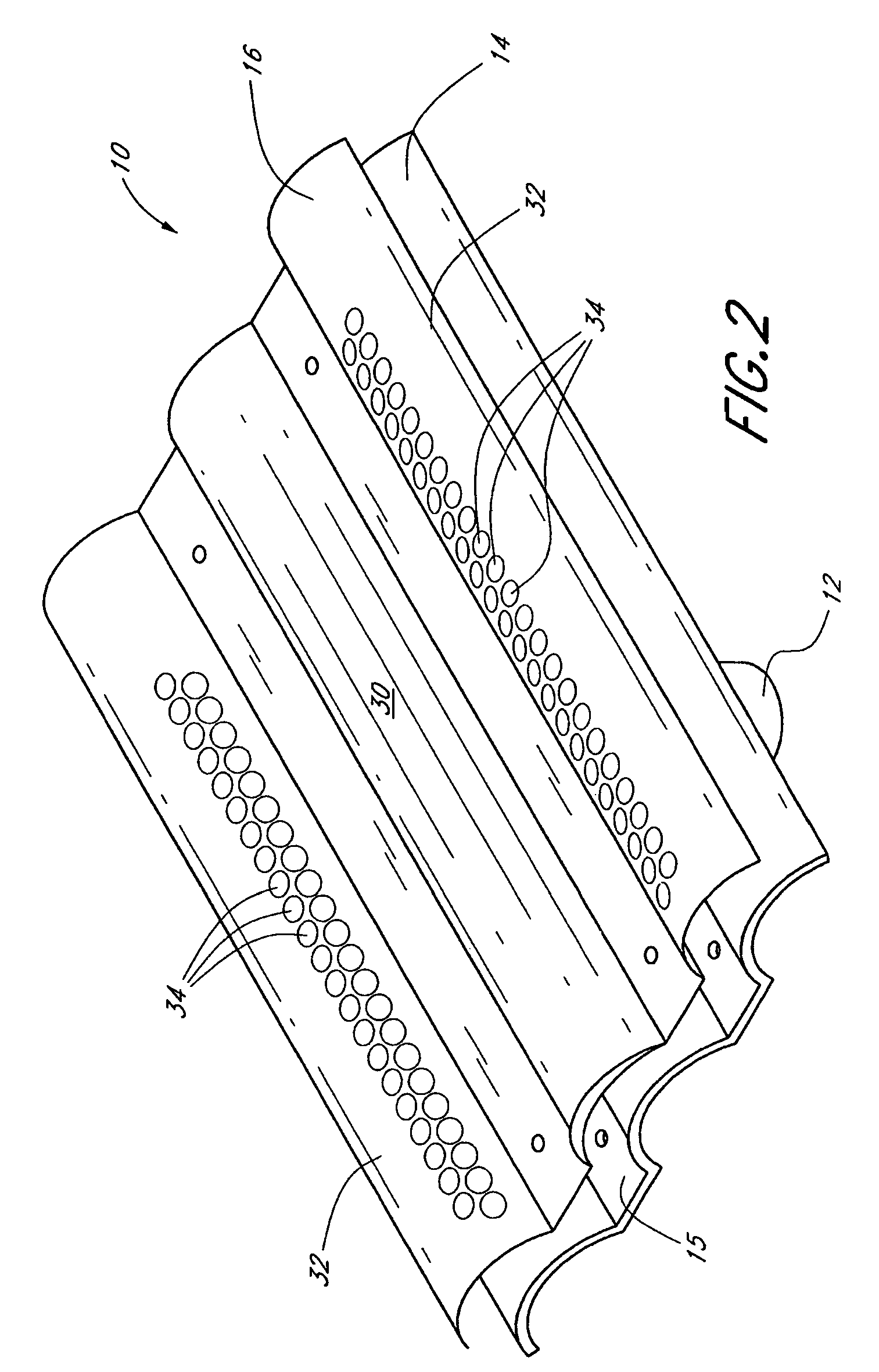
[0032]One aspect of the invention provides a roof vent including a metallic cover and a plastic body. A metal is typically more resistant to the elements than a plastic material. On the other hand, the latter is less expensive than the former and does not rust. Since the cover is more exposed to the elements than the intermediate member, the combination of a metallic cover and a plastic body enhances the lifetime of the roof vent while reducing the overall manufacturing cost. Another aspect of the invention provides a cover releasably connected to the remainder of the vent body, which allows replacing a damaged cover while re-using an undamaged vent body. Yet another aspect of the invention provides modularity of connectors and adapters, which allows a standardized roof vent to fit various sizes and configurations of stack vents.

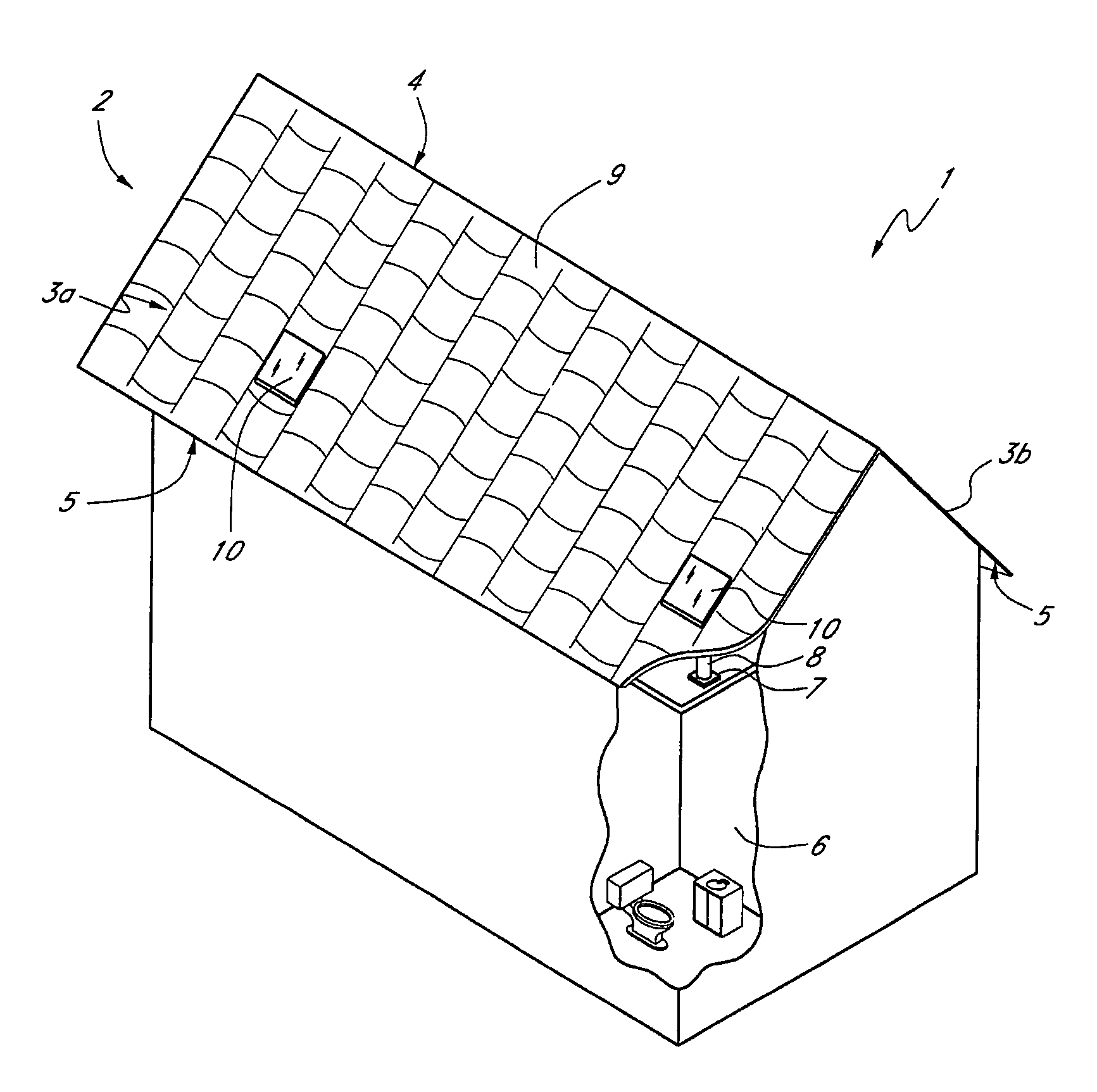
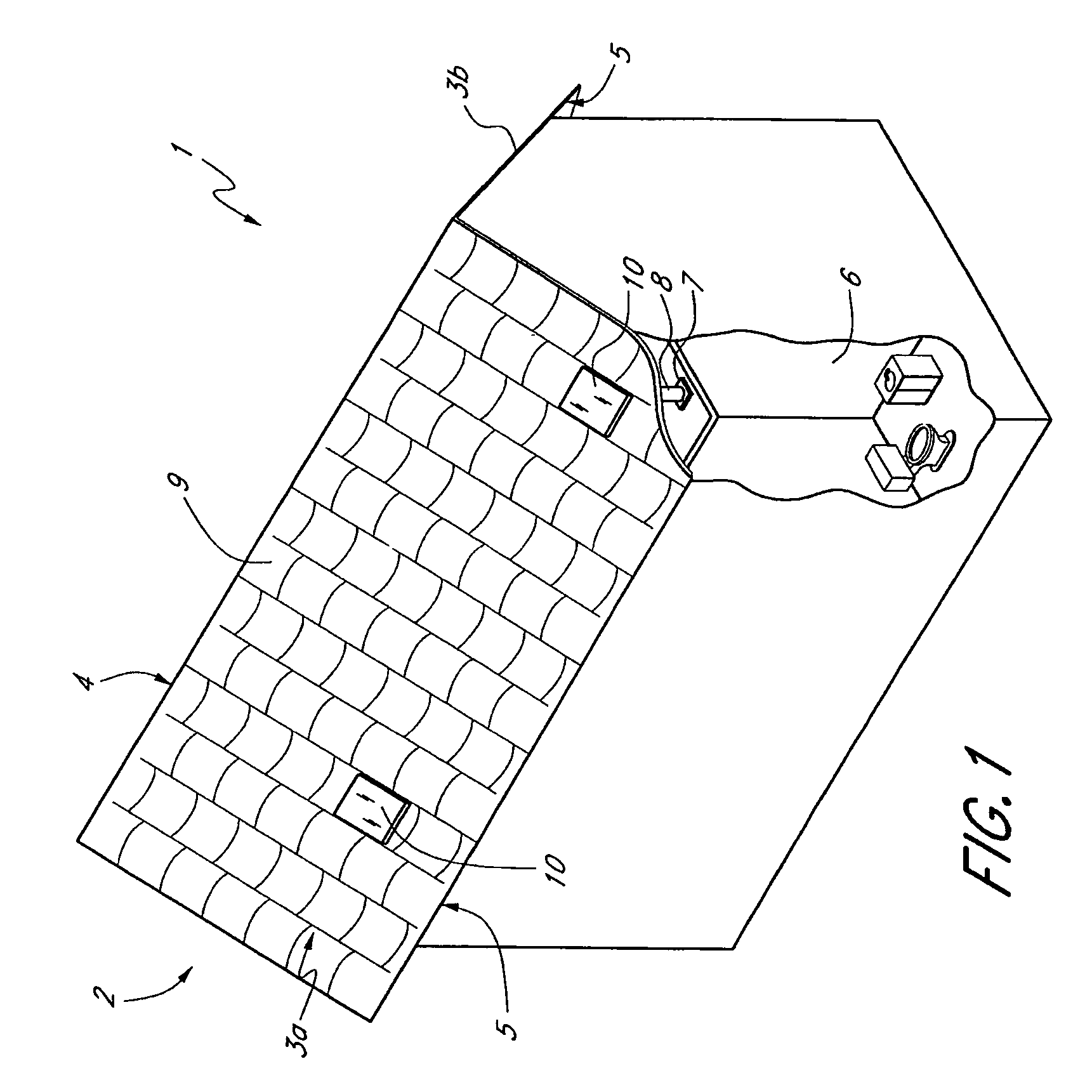
[0033]FIG. 1 shows a building 1 with a roof 2 according to one embodiment. The roof 2 comprises two fields 3a and 3b that are joined at their upper ends to ...


PUM


Abstract

A vent for a tile roof is disclosed. The vent includes a first member preferably substantially formed of a metal, a second member preferably substantially formed of a plastic material, and a connector attached to the underside of the second member. The second member is positioned below and spaced apart from the first member. The first and second members together define a ventilation gap therebetween. The first member and second member are preferably releasably connected to each other. The connector is configured to connect with an air conduit. The connector is further configured to be compatible with a plurality of sizes and types of air conduits. The ventilating access and the connector are together configured to permit airflow between above the roof and the air conduit.

Description

CLAIM FOR PRIORITY[0001]This application claims the priority benefit under 35 U.S.C. §119(e) of Provisional Application Ser. No. 60 / 709,856, filed Aug. 20, 2005. The full disclosure of this priority application is incorporated herein by reference.BACKGROUND OF THE INVENTION[0002]1. Field of the Invention[0003]This invention relates to roof vents, and more particularly for vents adapted for use on a tile roof.[0004]2. Description of the Related Art[0005]Known systems for venting roofs employ vents that are substantially formed of a single material. Some roof-vents are formed substantially of plastic, which is inexpensive and highly impact resistant, but degrades relatively easily when exposed to rain, snow, and the sun. In particular, the cover of a roof-vent is continually exposed to the elements and may degrade more rapidly than the rest of the vent. Other roof-vents are formed substantially of metal, which is more resistant to the elements but is expensive and susceptible to rust,...

Claims


Application Information

Patent Timeline
Patent Type & Authority Patents(United States)
IPC IPC(8): F24F7/02
CPCE04D1/30E04D13/17F24F7/02E04D2001/309
Inventor O'HAGIN, HARRY T.
Owner OHAGIN CAROLINA STOLLENWERK
Why Eureka
Try Eureka