Surgical instrument

a surgical instrument and a technology for living tissue, applied in the field of surgical instruments, can solve the problems that and the living tissue cannot be grasped (compressed) by a strong for

Active Publication Date: 2011-03-15
OLYMPUS CORP
View PDF18 Cites 1116 Cited by
  • Summary
  • Abstract
  • Description
  • Claims
  • Application Information

AI Technical Summary

Problems solved by technology

However, in this conventional surgical instrument, there is a problem that the living tissue cannot be grasped (compressed) by a strong force because the living tissue is grasped by the round bar-shaped horn and the arc-shaped sectioned open / close cover.
However, also in this conventional surgical instrument, there is a problem that the living tissue cannot be grasped (compressed) by a strong force because the living tissue is grasped by the round bar-shaped horn and the grasping member.

Method used


Image

  • Surgical instrument
  • Surgical instrument
  • Surgical instrument

Examples


first embodiment

[0041]First, a surgical instrument according to the present invention will be explained with reference to FIG. 1 to FIG. 8.

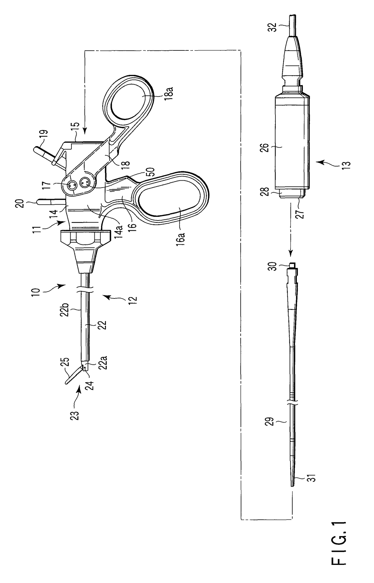
[0042]As shown in FIG. 1, a surgical instrument 10 has an operation area 11, an insertion area 12 which is attachable to and detachable from the insertion area 11, a transducer unit 13 which is detachably inserted into the insertion area 12 from the proximal end portion of the operation area 11.

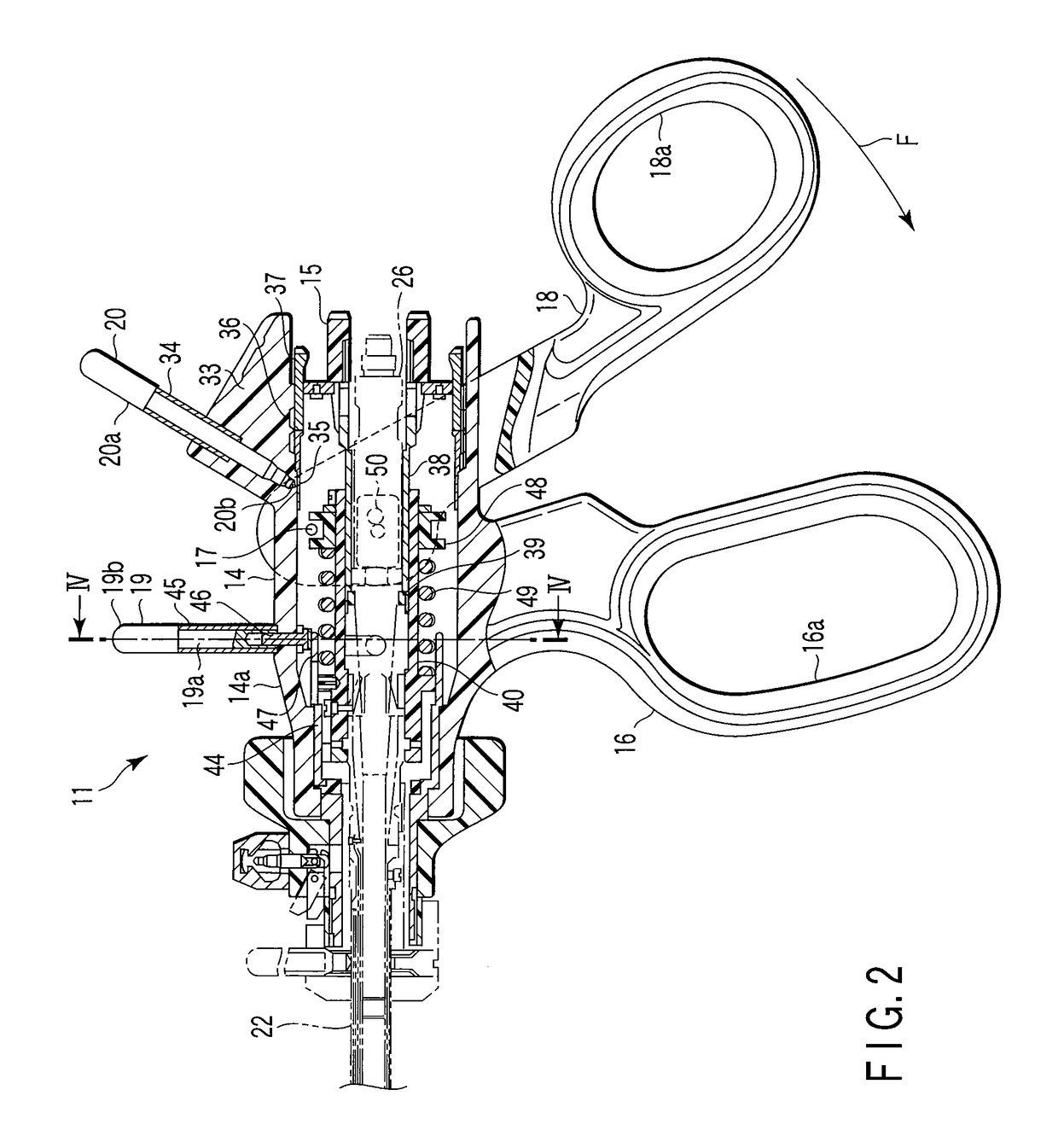
[0043]The operation area 11 has an operation area main body 14 having a cylindrical casing 14a. The proximal end portion of the operation area main body 14 is provided with a transducer unit connector 15 to which the transducer unit 13 is connected. A fixed handle 16 is integrally provided to the outer circumferential surface of the casing 14a of the operation area main body 14.

[0044]A movable handle 18 is provided to the casing 14a of the operation area main body 14 with a pivot 17. A finger insertion hole 16a is formed in the fixed handle 16, and fingers excepting the t...

second embodiment

[0079]FIG. 9A is a longitudinal sectional view of a surgical treatment area of the surgical instrument according to the present invention. FIG. 9B is a transverse sectional view along a line of IXB-IXB in FIG. 9A.

[0080]In this embodiment, in a pair of first electrodes 73 on both sides of a pad member 72 in the ultrasonic surgical treatment area member 25b of a first grasping member 71, each of a pair of surface areas to face a pair of second electrodes 75 of a second grasping member 75 is inclined (to 45°, for example) to form an inclined surface 73a with respect to a line CL passing the center of the pad member 72 and extending along the pivotal movement direction of the first grasping member 71. A row of substantially sawtooth-like teeth 74 is formed at the outer end portion of the inclined surface 73a of each first electrode 73 to grasp a living tissue without slipping.

[0081]Further, in this embodiment, the second grasping member 75 is provided by machining the ultrasonic vibrati...

third embodiment

[0087]FIG. 10A is a longitudinal sectional view of a surgical treatment area of the surgical instrument according to the invention. FIG. 10B is a transverse sectional view along a line of XB-XB in FIG. 10A.

[0088]In this embodiment, a pair of first electrodes 83 in both sides of a pad member 82 in the ultrasonic surgical treatment area member 25b of a first grasping member 81 is projected along and in parallel to a line CL passing the center of the pad member 82 and extending along the moving direction of the first grasping member 81. A row of substantially sawtooth-like teeth 84 is formed on each projected end surface of the pair of first electrodes 83 to grasp a living tissue without slipping.

[0089]Further, in this embodiment, a second grasping member 88 is provided by machining the ultrasonic vibrating portion 31, which has conventionally the circular cross section, at the distal end portion of the probe 29, into a non-circular cross section (rectangular), by a well-known machinin...


PUM


Abstract

A surgical instrument has a first grasping member, a second grasping member which is provided to the first grasping member to open and close to the first grasping member, and grasps a living tissue between them, an ultrasonic coagulation-cutting unit which includes an ultrasonic vibrating portion provided in one of the first and second grasping members and connected to an ultrasonic transducer to generate ultrasonic vibration, and a pressing portion provided in the other of the first and second grasping members, and facing the ultrasonic vibrating portion, the pressing portion and the ultrasonic vibrating portion pressing the living tissue between them, and a high-frequency coagulation unit which includes a first electrode provided in the first grasping member, and a second electrode provided in the second grasping member, the first electrode and the second electrodes facing each other to coagulate the living tissue.

Description

CROSS-REFERENCE TO RELATED APPLICATIONS[0001]This application is based upon and claims the benefit of priority from prior Japanese Patent Application No. 2006-184663, filed Jul. 4, 2006, the entire contents of which are incorporated herein by reference.BACKGROUND OF THE INVENTION[0002]1. Field of the Invention[0003]The present invention relates to a surgical instrument, which grasps a living tissue, and coagulates and cuts the tissue by ultrasonic vibration and high-frequency current.[0004]2. Description of the Related Art[0005]Each of an ultrasonic instrument using ultrasonic vibration and a high-frequency instrument using a high-frequency current is known as a surgical instrument. An ultrasonic instrument can coagulate and cut a living tissue by heating the tissue with ultrasonic vibration. A high-frequency instrument can coagulate and cut a living tissue by touching an electrified electrode to the living tissue.[0006]Surgical instruments which can treat a living tissue by using b...

Claims


Application Information

Patent Timeline
Patent Type & Authority Patents(United States)
IPC IPC(8): A61B18/18
CPCA61B18/1445A61B17/32A61B17/320092A61N7/02A61B2018/00589A61B2018/146A61B2018/0019A61N1/328A61B2017/320093A61B2017/320095A61B18/12A61B18/14A61B18/16
Inventor MASUDA, SHINYAMIYAZAWA, TAROTANIGUCHI, KAZUNORIOKABE, HIROSHI
Owner OLYMPUS CORP
Why Eureka
Try Eureka