Vehicular steering wheel and column assembly including torsional damper device

a technology of torsional damper and steering wheel, which is applied in the direction of vehicular safety arrangements, pedestrian/occupant safety arrangements, transportation and packaging, etc., can solve the problems of minor torsional vibration, undesirable, perceptible to drivers, etc., and the device has been limited in various respects

Inactive Publication Date: 2011-03-22
GM GLOBAL TECH OPERATIONS LLC
View PDF11 Cites 49 Cited by
  • Summary
  • Abstract
  • Description
  • Claims
  • Application Information

AI Technical Summary

Benefits of technology

A steering wheel and column assembly is provided for deployment on a vehicle. In one embodiment, the steering wheel and column assembly comprises: (i) a steering column housing, (ii) a rotatable steering assembly, and (iii) a torsional damper device. The rotatable steering assembly includes a steering column shaft, which is rotatably coupled to the steering column housing, and a steering wheel, which is fixedly coupled to the steering column shaft. The torsional damper device includes a stator body, which is fixedly coupled to the steering column housing, and a rotor body, which is fixedly coupled to the rotatable steering assembly. The rotor body frictionally engages the stator body to produce a predetermined coulomb torque frictional resistance.
A supplemental inflatable restraint (SIR) coil assembly is also provided for deployment within a steering wheel and column assembly of the type that includes a steering column housing, a steering column shaft rotatably coupled to the steering column housing, a steering wheel fixedly coupled to the steering column shaft, and an SIR module mounted on the steering wheel. In one embodiment, the SIR coil assembly includes: (i) a stator body configured to be fixedly coupled to the steering column housing, (ii) a rotor body configured to be fixedly coupled to at least one of the steering wheel and the steering column shaft, and (iii) an SIR coil disposed between the stator body and the rotor body and configured to be electrically coupled to the SIR module. The rotor frictionally engages the stator body to produce a predetermined coulomb torque frictional resistance between approximately 0.1 Newton meters and approximately 0.4 Newton meters

Problems solved by technology

Despite this, conventional steering wheel and column assemblies may still permit minor torsional vibrations to be transmitted through the steering column shaft to the steering wheel.
Such vibrations may be produced by various periodic sources at the rotating corners of the vehicle (e.g., tires, wheels, brake rotors, bearing hub assemblies, etc.), including such conditions as imbalance and non-uniform tires, and consequently may be produced even when the vehicle is traveling over a relatively smooth road.
Although this rotational movement is relatively minor, it is readily perceptible to a driver and consequently undesirable.
Devices have been produced that attempt to minimize SRS by providing a clamping force around the steering wheel shaft; however, such devices have been limited in various respects.
For example, such devices tend to be inherently resilient for small angular displacements and consequently store, rather than dissipate, kinetic energy.

Method used


Image

  • Vehicular steering wheel and column assembly including torsional damper device
  • Vehicular steering wheel and column assembly including torsional damper device
  • Vehicular steering wheel and column assembly including torsional damper device

Examples


Embodiment Construction

The following detailed description is merely exemplary in nature and is not intended to limit the invention or the application and uses of the invention. Furthermore, there is no intention to be bound by any expressed or implied theory presented in the preceding technical field, background, brief summary or the following detailed description.

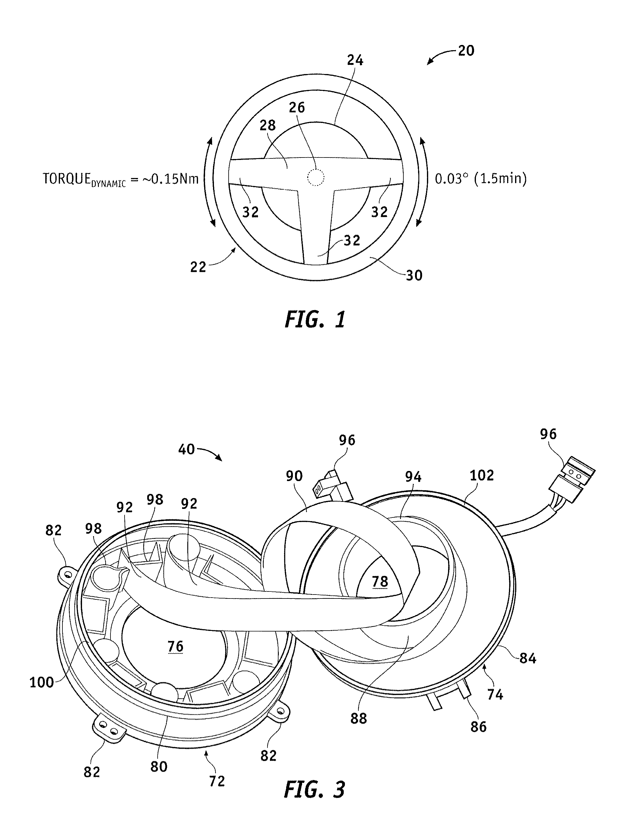
FIG. 1 is a simplified plan view of a steering wheel and column assembly 20 illustrating the occurrence of smooth road shake (referred to herein as “SRS”) with dynamic motions at the threshold of driver detection; e.g., of approximately 1.5 minutes at or near frequencies ranging from approximately 8 to 20 hertz as discussed more fully below. Steering wheel and column assembly 20 includes a steering wheel 22, a steering column housing 24, and a steering column shaft 26 (shown in phantom). Steering column housing 24 is fixedly mounted to a base mounting structure provided on a host vehicle (not shown). Steering wheel 22 includes a steering wheel r...


PUM


Abstract

A steering wheel and column assembly is provided for deployment on a vehicle. In one embodiment, the steering wheel and column assemblies comprises: (i) a steering column housing, (ii) a rotatable steering assembly, and (iii) a torsional damper device. The rotatable steering assembly includes a steering column shaft, which is rotatably coupled to the steering column housing, and a steering wheel, which is fixedly coupled to the steering column shaft. The torsional damper device includes a stator body, which is fixedly coupled to the steering column housing, and a rotor body, which is fixedly coupled to the rotatable steering assembly. The rotor body frictionally engages the stator body to produce a predetermined coulomb torque frictional resistance.

Description

TECHNICAL FIELDThe present invention generally relates to vehicular steering systems and, more particularly, to a steering wheel and column assembly including a torsional damper device.BACKGROUNDIt is now common for a vehicle's steering wheel to support various electrical devices, such as audio system controls, a horn actuation switch, and a supplemental inflatable restraint (SIR) module. A contact plate may be employed to maintain electrical communication between the vehicle's electrical infrastructure and the audio system controls, the horn actuation switch, and other such steering-wheel mounted inputs. However, an SIR coil assembly is commonly employed to provide a more reliable hardwire connection with the SIR module. A generalized SIR coil assembly includes a stator body, a rotor body, and a flat ribbon cable coiled between the stator body and the rotor body (commonly referred to as an “SIR coil” or a “clock spring roll”). The stator body of the SIR coil assembly is fixedly att...

Claims


Application Information

Patent Timeline
Patent Type & Authority Patents(United States)
IPC IPC(8): B60R21/203
CPCB62D7/224F16F7/04
Inventor OBLIZAJEK, KENNETH L.WRIGHT, CARL T.
Owner GM GLOBAL TECH OPERATIONS LLC
Why Eureka
Try Eureka