RF connector mounting means

a technology for mounting means and rf connectors, which is applied in the direction of coupling device connections, printed circuit manufacturing, coupling device details, etc., can solve the problems of difficult to achieve exact contact and assembly, limited space available in a lateral direction for the connectors, and adverse effects, so as to achieve small tolerance between the rf connectors.

Inactive Publication Date: 2011-03-22
LAIRD TECH INC
View PDF55 Cites 4 Cited by
  • Summary
  • Abstract
  • Description
  • Claims
  • Application Information

AI Technical Summary

Benefits of technology

[0005]An object of the invention is to provide a quick, secure, and / or space-saving mounting of RF connectors to a module, such as an antenna module, to ensure contacting of the RF connectors to the antenna module.
[0011]Ground pads in the form of for example small ground legs or protrusions protrude from the upper surface of the base plate, which serve for contacting the substrate as well as taking up forces. The small ground legs thus take up the forces and bending moments influencing during assembly and loading. The small ground legs are to this end preferably provided laterally outside of the frame. Also the coding means, which in particular can be extending coding pins, serve to take up forces and bending moments to avoid or at least minimizing loading of the inner conductors of the RF connectors.
[0013]The tolerances between the RF connectors can be kept small by the use of the base plate, so that a very space saving, narrow RF connector device is made possible. In case of using SMB connectors, for example, tolerances for the distances of the inner conductors from for example 9+ / −0.02 mm can hereby be achieved.

Problems solved by technology

For the contacting of several RF connectors for more complex antenna modules exact positioning of the connectors is necessary since the performance can be adversely affected if the RF connectors are misaligned.
However, there is generally only a limited space available in a lateral direction for the connectors, such as a hole with the size of 15×15 or 17×17 mm, in which four connectors are to be fitted.
Exact contacting and assembly are therefore often difficult to achieve.

Method used


Image

  • RF connector mounting means
  • RF connector mounting means
  • RF connector mounting means

Examples


Embodiment Construction

[0026]In the following a detailed description of preferred embodiments of the present invention will be given. It will be realized that the directions given in this description, such as upper and lower, are intended for non-limiting explanation only and refer to the directions shown in the figures.

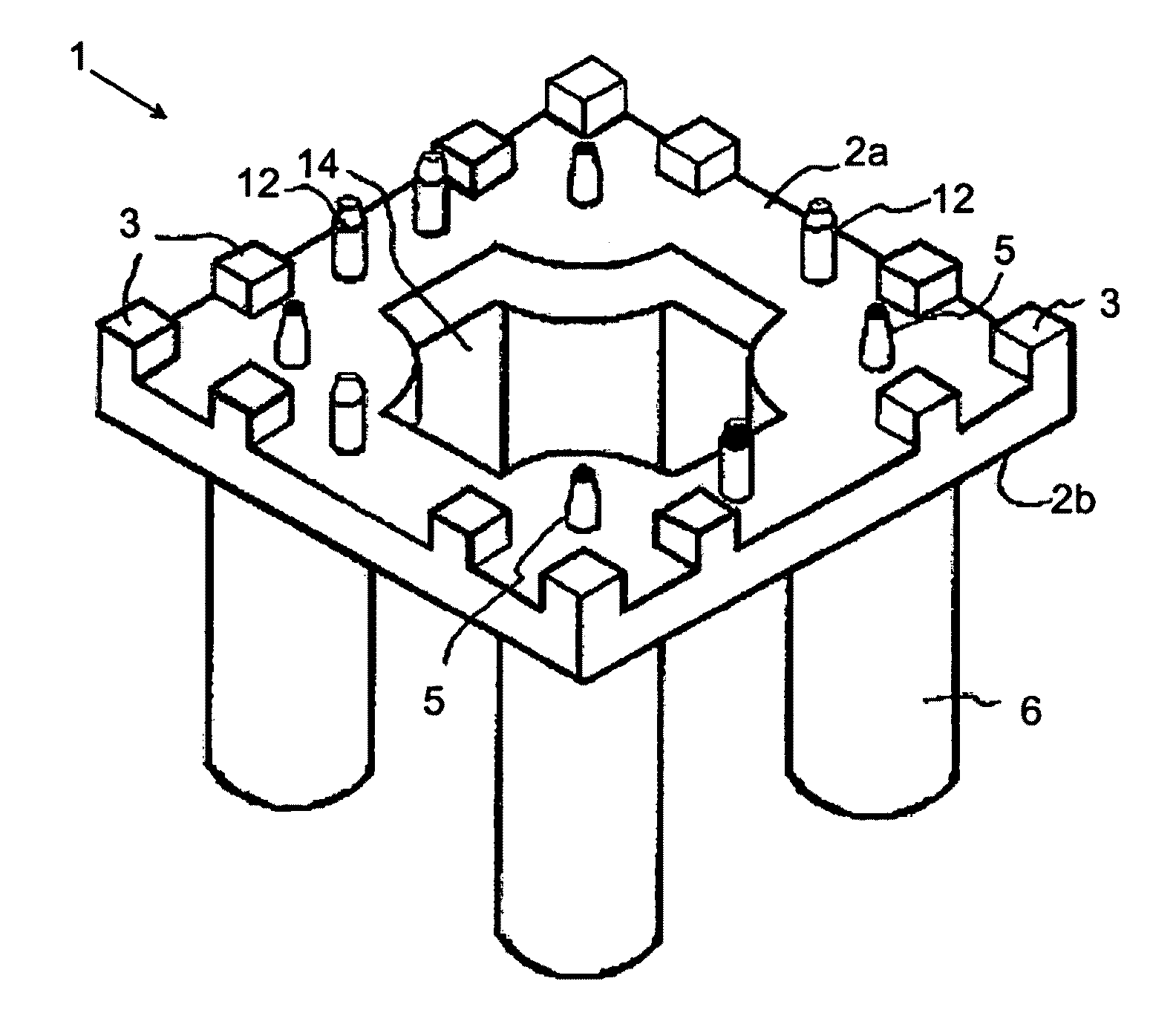
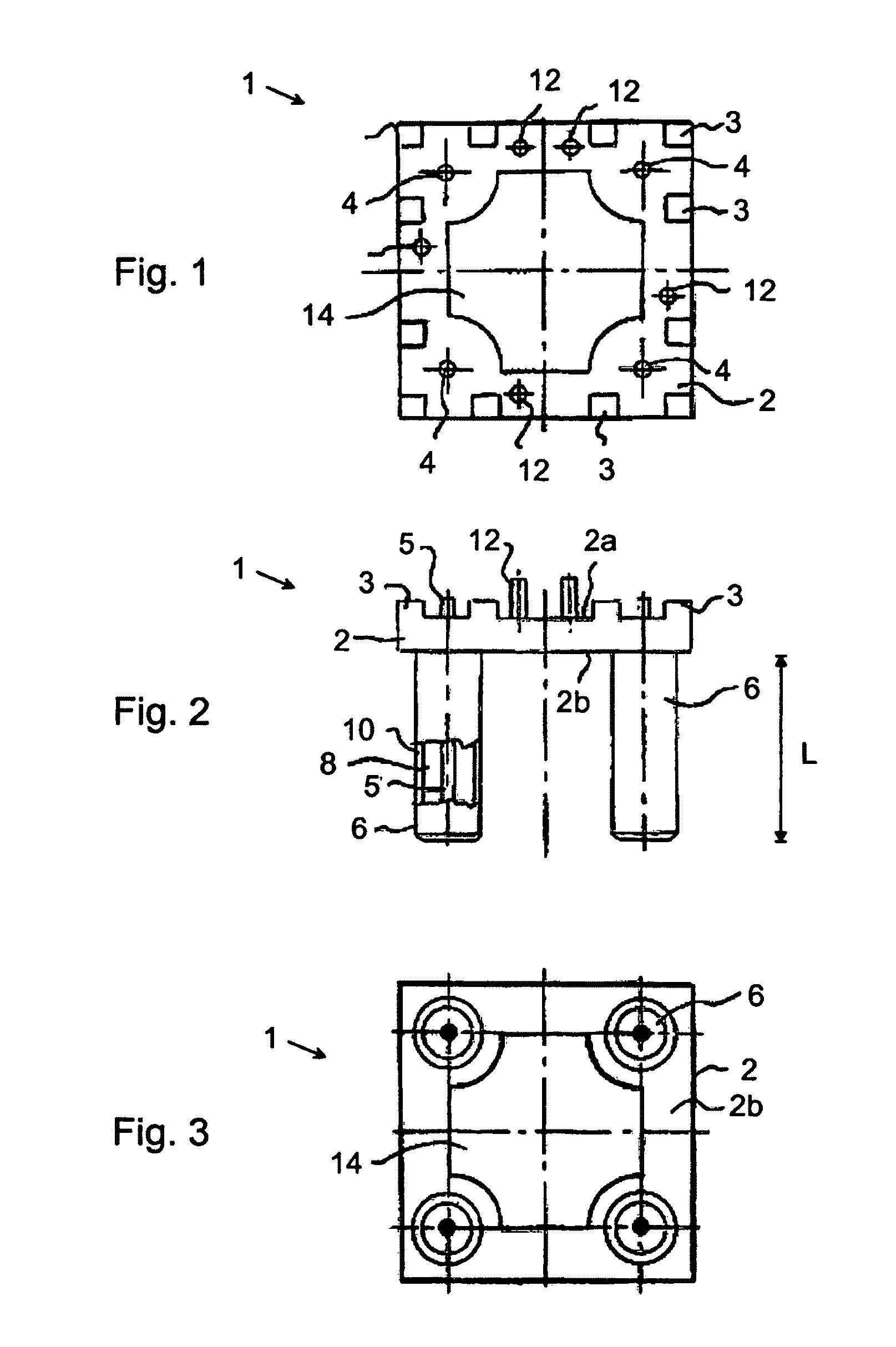
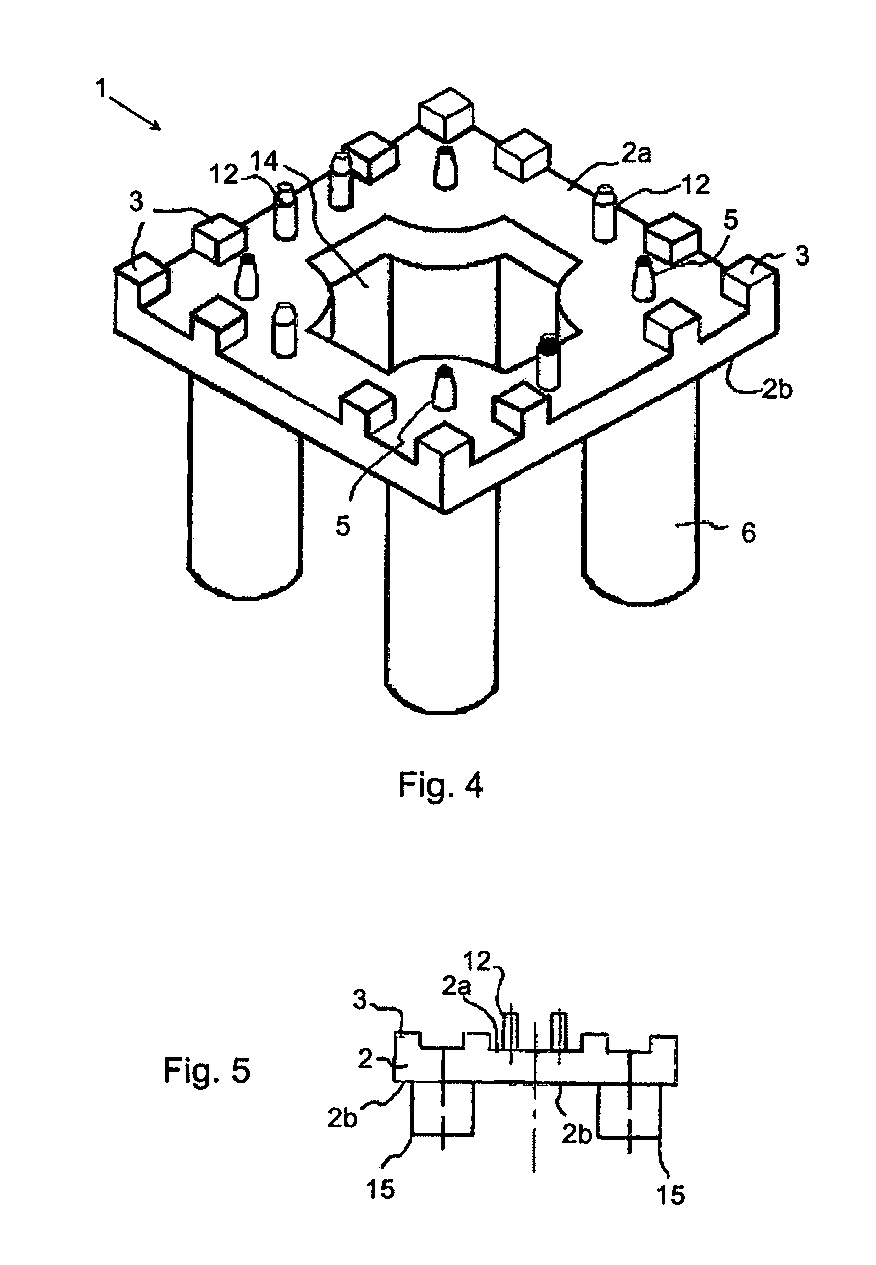
[0027]An RF connector device or frame 1 comprises in accordance with FIGS. 1-4 a base plate 2 made of metal material having an upper surface 2a and a lower surface 2b. Ground pads in the form of small metal ground legs or protrusions 3 extend from the upper surface 2a of the base plate 2. These legs are preferably integral with the rest of the base plate, thus forming a unitary unit. Through holes 4 are provided in the base plate 2, which in the shown embodiment are four symmetrically arranged holes in the corner areas of the base plate. These through holes extend from the upper surface 2a down to the lower surface 2b and are arranged to receive a respective inner conductor 5 of RF connect...


PUM

PropertyMeasurementUnit
mutual distanceaaaaaaaaaa
sizeaaaaaaaaaa
sizeaaaaaaaaaa

Abstract

A mounting means (1) for RF connectors (6) to be connected to a substrate (20) comprises a base plate (2) having an upper surface (2a) and a lower surface (2b). The base plate exhibits electrically leading material at least on part of its surfaces. Ground pads (3) are provided on the upper surface (2a) of the base plate (2) and arranged for support and electrical contacting to the substrate. A plurality of through holes (4) for electrically isolated reception of inner conductors (5) of RF connectors. By means of this mounting means, quick, secure, and space-saving mounting of RF connectors is achieved.

Description

FIELD OF INVENTION[0001]The present invention relates generally to a means for mounting RF connectors to for example a printed circuit board and more particularly to a mounting means, which facilitates mounting of RF connectors with high precision. The present invention also relates to an antenna module comprising such mounting means, and a method of mounting RF connectors.BACKGROUND[0002]Antenna modules for vehicles are generally attached to the roof; the antenna module housing is to this end attached to the roof by means of for example a screw connection and is connected via connectors, such as RF connectors, which generally extend through the vehicle roof and into the interior of the vehicle.[0003]For the contacting of several RF connectors for more complex antenna modules exact positioning of the connectors is necessary since the performance can be adversely affected if the RF connectors are misaligned.[0004]However, there is generally only a limited space available in a lateral...

Claims


Application Information

Patent Timeline
Patent Type & Authority Patents(United States)
IPC IPC(8): H01R12/00H01R13/646
CPCH01Q1/3275H01R13/64H01R24/50Y10T29/4913H01R2201/02H01R2201/26H01R2103/00H01R12/70H01R13/646
Inventor STEINKAMP, ULRICHRODE, NILS
Owner LAIRD TECH INC
Why Eureka
Try Eureka