
Shrimp peeling, deveining and head removal tool

a technology for deveining and shrimp, which is applied in the field of deveining and shrimp head removal tools, can solve the problems of time-consuming and awkward use of tools

Inactive Publication Date: 2011-03-22
GOODMAN DANNY
View PDF7 Cites 15 Cited by
  • Summary
  • Abstract
  • Description
  • Claims
  • Application Information

AI Technical Summary

Problems solved by technology

These tools tend to be awkward and time-consuming to use.

Method used


Image

  • Shrimp peeling, deveining and head removal tool
  • Shrimp peeling, deveining and head removal tool
  • Shrimp peeling, deveining and head removal tool

Examples


Embodiment Construction

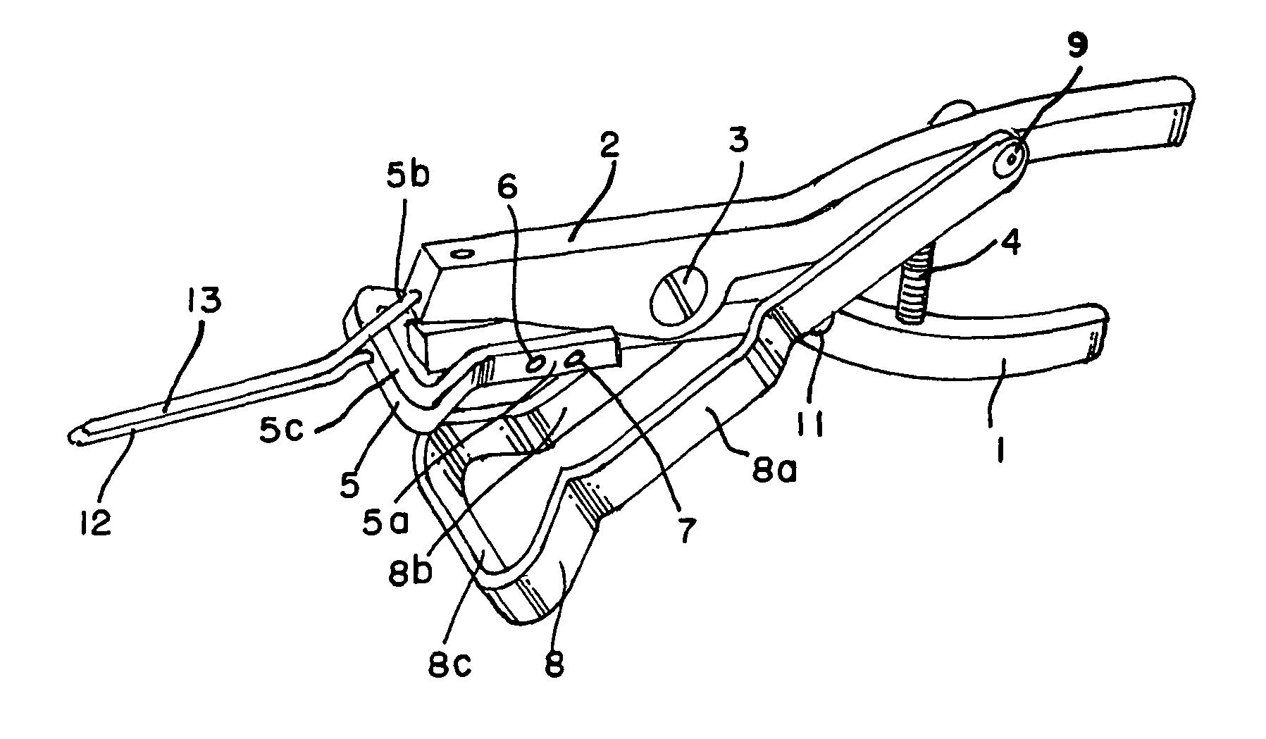
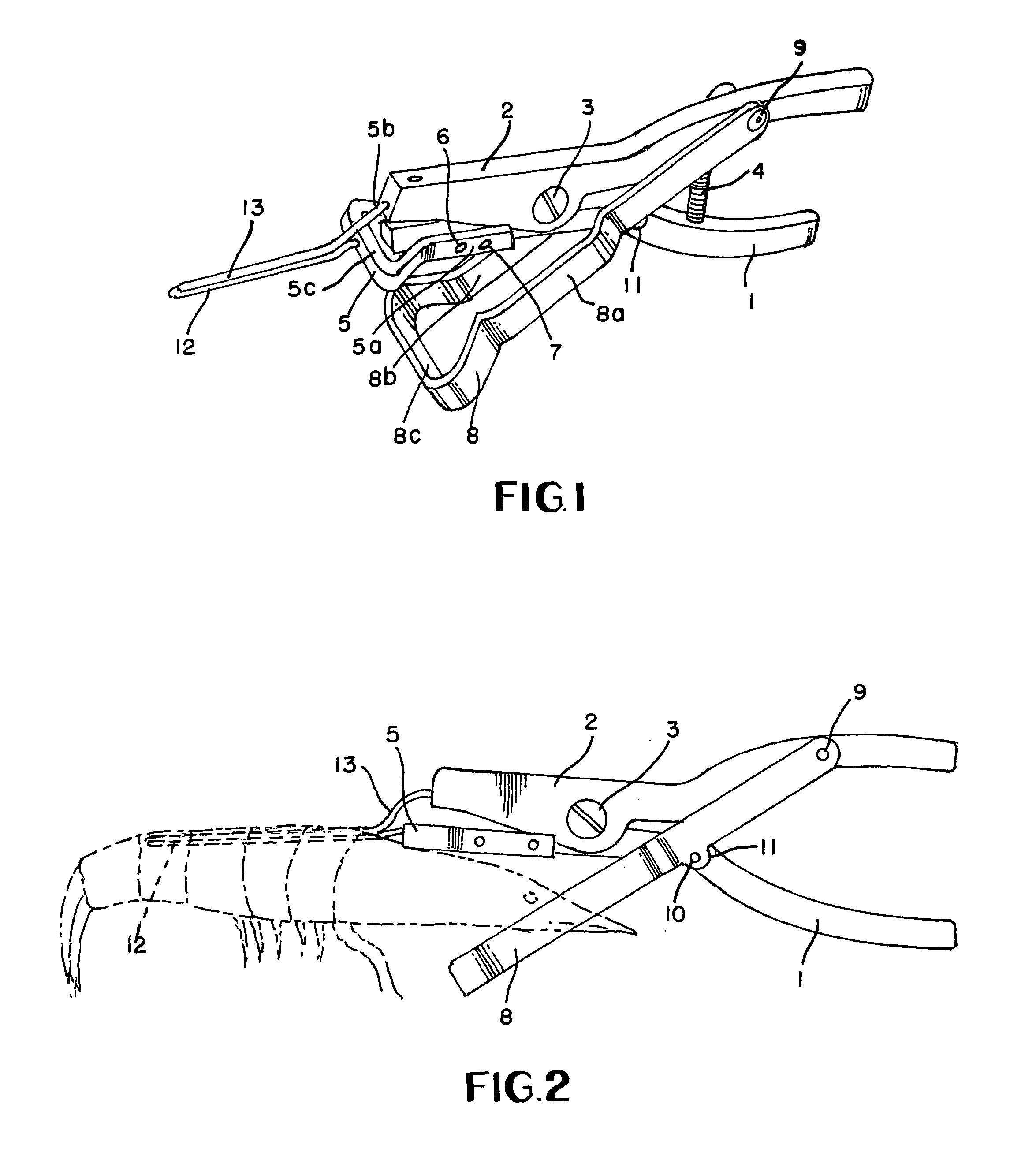
[0007]In the drawings and with particular reference to FIG. 1, the numerals 1 and 2 identify the lower and upper handles of the tool, respectively, which are pivotally interconnected by means of bolt 3 arrangement. Lower handle 1 and upper handle 2 are urged apart by compression spring 4.

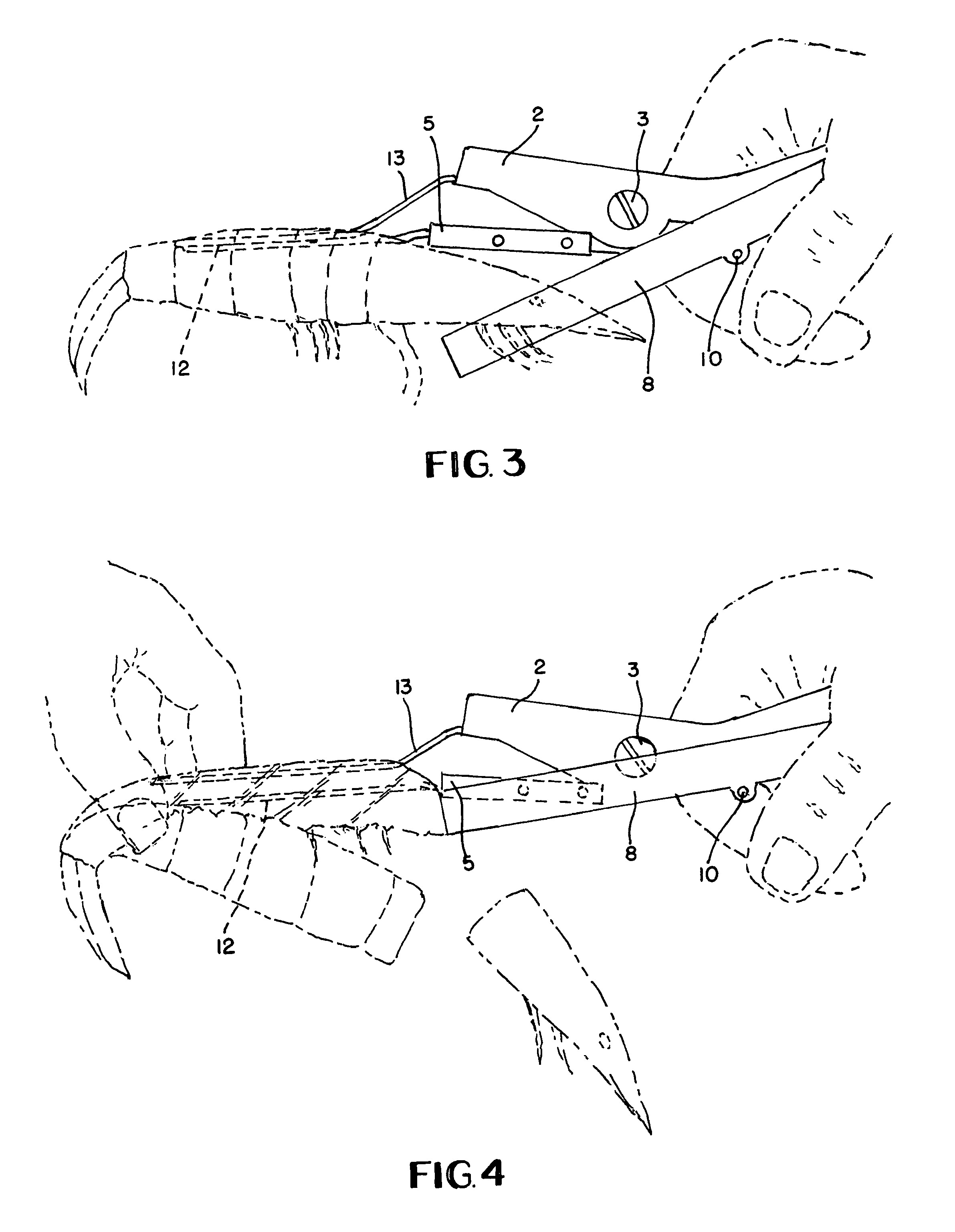
[0008]For the purpose of removing the shrimp head, upper blade 5 is provided and includes parallel extensions 5a and 5b and enlarged head portion 5c. Upper blade 5 is attached to lower handle 1 on one side by means of screws 6 and 7 which interconnect parallel extension 5a and lower handle 1. Although not shown in the drawings, identical connector means is employed with respect to parallel extension 5b and lower handle 1. To complete the head removal device, lower blade 8 is provided and includes offset side extensions 8a and 8b and enlarged head portion 8c. The free ends of side extensions 8a and 8b are pivotally connected to upper handle 2 by means of pivot pin 9. In addition, side extensions 8a a...


PUM


Abstract

A shrimp peeling, deveining and head removal tool including a pair of handles pivoted together and urged apart by a compression spring, an upper blade attached to lower handle and a lower blade pivoted to both handles with the ends of the blades of substantially of the same configuration and disposed in close proximity one within the other when the handles are compressed, and a pair of tines extending, respectively, from the upper handle and the upper blade and being in contact substantially the entire length thereof when the handles are not compressed.

Description

[0001]This is a division of patent application Ser. No. 11 / 895,580 filed Aug. 27, 2007, now U.S. Pat. No. 7,527,549.BACKGROUND OF THE INVENTION[0002]This invention is for a shrimp peeling, deveining and head removal tool. Many known tools require a two-step process by which the head is separated first by hand from the shrimp body and then a second operation is undertaken to remove the vein across the shrimp's back while simultaneously removing the shrimp shell. Other shrimp hand tools involve a three-step process to first remove the head and then undertaking a second step of manually manipulating the tool to remove the shell and, following this, scraping the vein away from the shrimp body. These tools tend to be awkward and time-consuming to use.BRIEF SUMMARY OF THE INVENTION[0003]By this invention, a shrimp peeling, deveining and head removal tool is provided and includes upper and lower handles pivotally interconnected and urged apart by means of a compression spring with an upper...

Claims


Application Information

Patent Timeline
Patent Type & Authority Patents(United States)
IPC IPC(8): A22C29/02
CPCA22C29/024
Inventor GOODMAN, DANNY
Owner GOODMAN DANNY
Learn More