Methods, devices and systems for forming magnetic anastomoses

a magnetic anastomosis and magnetic technology, applied in the field of magnetic anastomosis, can solve the problems of not being widely used or accepted, proposed couplers or connectors have failed to duplicate the success of suture, and limited success

Inactive Publication Date: 2011-03-22
MEDTRONIC INC
View PDF192 Cites 168 Cited by
  • Summary
  • Abstract
  • Description
  • Claims
  • Application Information

AI Technical Summary

Benefits of technology

[0008]According to one embodiment, the invention provides a method for forming an anastomosis between first and second hollow bodies using magnetic force. The method includes steps of providing first and second anastomotic components that are magnetically attracted to each other and are configured to be secured to first and second hollow bodies. The first component is mounted on a delivery device while the second anastomotic component is secured to the second hollow body and then mounted on the delivery device. The first anastomotic component is secured to the first hollow body, and magnetism is used to couple the first and second anastomotic components and form an anastomosis between the first and second hollow bodies.

Problems solved by technology

Many anastomotic couplings have been proposed as substitutes for a conventional, handsewn sutured anastomosis; they have had limited success.
In the vascular field, most of the proposed couplers or connectors have failed to duplicate the success of sutured anastomoses and, as such, have not been widely used or accepted.
Among the drawbacks associated with proposed anastomotic couplers are failure to achieve an acceptable patency rate, insecure or inadequate attachment of the coupler to the vessels, and the inability to produce a good anastomosis on a repeated basis.

Method used


Image

  • Methods, devices and systems for forming magnetic anastomoses
  • Methods, devices and systems for forming magnetic anastomoses
  • Methods, devices and systems for forming magnetic anastomoses

Examples


Embodiment Construction

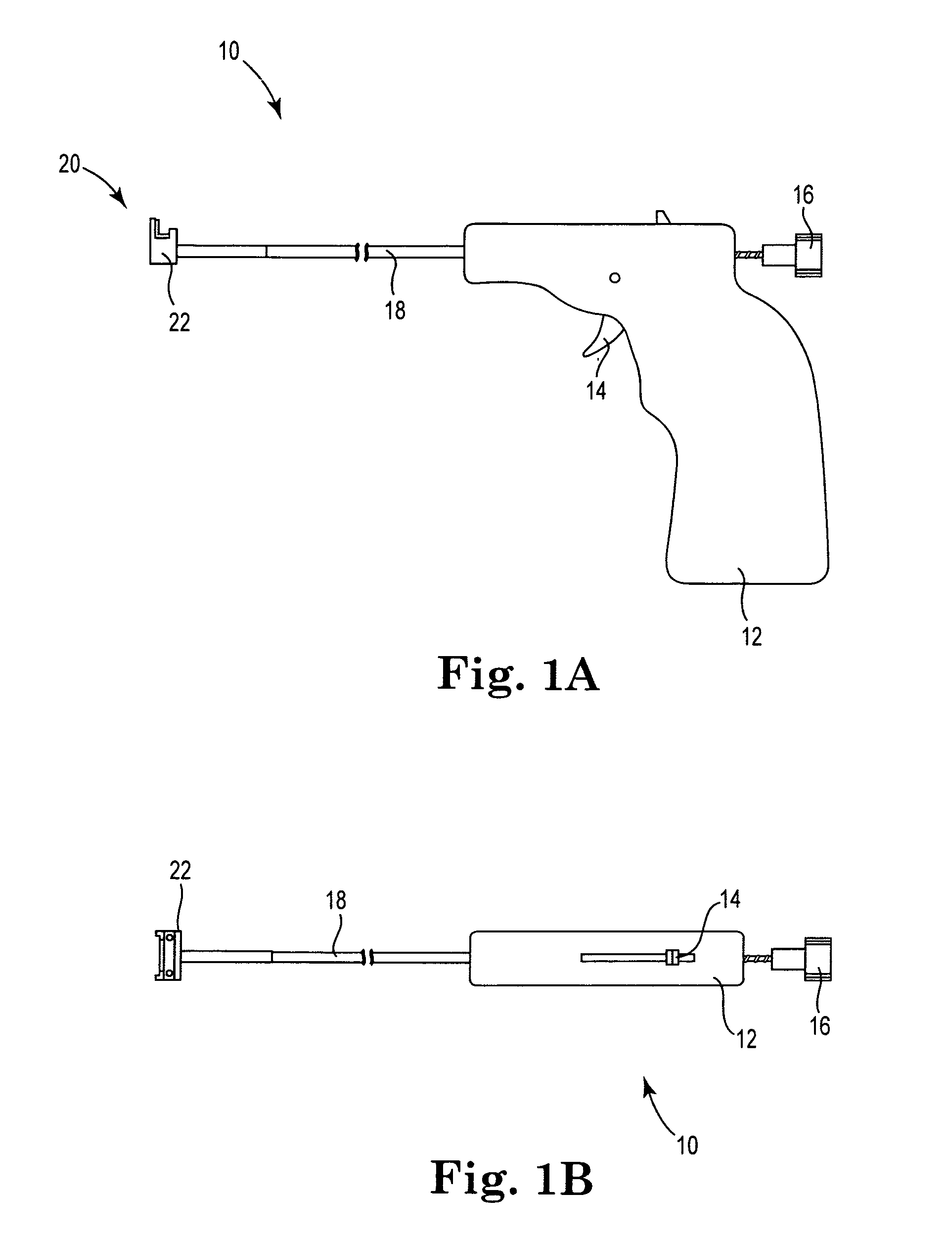
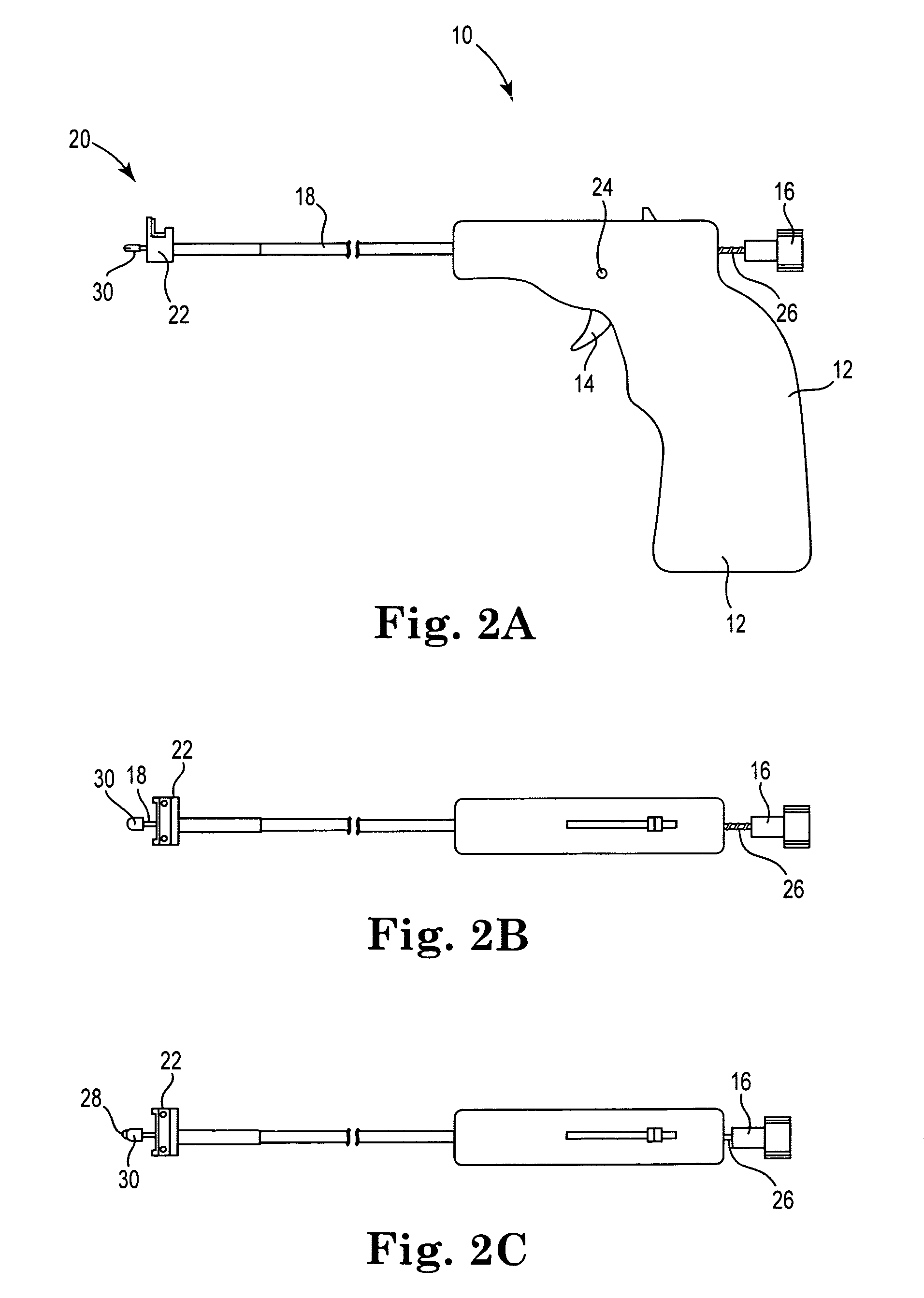
[0035]FIG. 1 shows an anastomotic delivery device 10 having a handle 12, first and second actuators 14, 16, and a shaft 18. The distal end of the delivery device 10 is indicated by the reference numeral 20 and is constructed to deploy a first anastomotic component that is configured to be coupled to a second anastomotic component, thereby forming a magnetic anastomosis. As used herein, the term anastomosis encompasses the connection of any two (or more) hollow anatomical structures, bodies, vessels, etc.

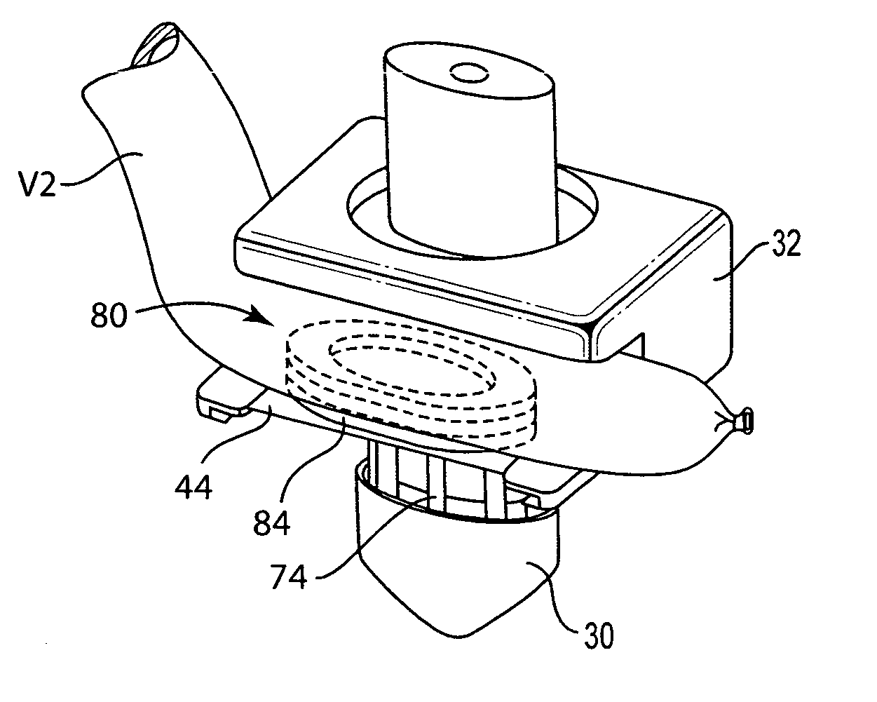
[0036]The distal end 20 of delivery device 10 is used to secure a first anastomotic component to a first vessel while supporting a second anastomotic component secured to a second vessel (the components and vessels not being shown in FIGS. 1A and 1B and 2A-2C). In the illustrated embodiment the distal end 20 includes a cradle 22, which is described in detail below with reference to FIGS. 3 and 4A-4C. The cradle 22 receives the second anastomotic component and a portion of the vessel ...


PUM

PropertyMeasurementUnit
magnetic forceaaaaaaaaaa
magnetismaaaaaaaaaa
ferromagneticaaaaaaaaaa

Abstract

Methods, devices and systems for forming magnetic anastomoses between two blood vessels. A first anastomotic component is removably supported by the distal end of a delivery device for attachment to a first vessel. The delivery device also supports a second anastomotic component that has been secured to a second blood vessel. The device is operated to secure the first component to the first vessel, couple the second component to the first component, and then release the components to complete the anastomosis. A robotic anastomosis system includes several robotic instruments that may be positioned through ports in a patient, used to secure an anastomotic component to a vessel, and then used to magnetically couple the components. Delivery devices for deploying magnetic anastomotic components include an actuator that uses magnetic repulsion to move the components into engagement with the inner and outer surfaces of the vessel wall. The anastomotic components are secured to the vessel wall by magnetic force and in addition may be secured by mechanical attachment.

Description

CROSS-REFERENCE TO RELATED APPLICATIONS[0001]The present application claims priority under 35 USC §119(e) from provisional application Ser. No. 60 / 323,923, filed Sep. 15, 2001. This application also claims priority under 35 USC §120 from the following applications: application Ser. No. 10 / 022,187, filed Dec. 13, 2001, application Ser. No. 09 / 915,226, filed Jul. 23, 2001, application Ser. No. 09 / 851,400, filed May 7, 2001, application Ser. No. 09 / 638,805, filed Aug. 12, 2000, and application Ser. No. 09 / 562,599, filed Apr. 29, 2000, now U.S. Pat. No. 6,352,543. The entire disclosure of each of the above-referenced patent applications is expressly incorporated herein by reference.BACKGROUND OF THE INVENTION[0002]1. Field of the Invention[0003]The invention relates to forming an anastomoses between hollow anatomical structures or bodies, such as blood vessels, and more particularly, to using magnetism to form such anastomoses.[0004]2. Description of Related Art[0005]Many anastomotic co...

Claims


Application Information

Patent Timeline
Patent Type & Authority Patents(United States)
IPC IPC(8): A61B17/08A61B17/00A61B17/04A61B17/064A61B17/11A61F2/00A61F2/06H01F41/02
CPCA61B17/0643A61B17/11H01F41/026A61B17/00491A61B17/0469A61B17/064A61B2017/00252A61B2017/1107A61B2017/1135A61B2017/1139A61F2/064A61F2002/30079A61F2210/009
Inventor CREWS, SAMUELSTINE, J. GREGOLSON, STEPHEN L.COLE, DAVID H.
Owner MEDTRONIC INC
Why Eureka
Try Eureka