Alcohol detection system

a detection system and alcohol technology, applied in the direction of computer control, program control, driver input parameters, etc., can solve the problems of system error in detecting drunk drivers, inability to eliminate illicit acts,

Active Publication Date: 2011-03-22
PANASONIC CORP
View PDF9 Cites 9 Cited by
  • Summary
  • Abstract
  • Description
  • Claims
  • Application Information

AI Technical Summary

Problems solved by technology

However, in detection of an alcohol drinking condition of a driver by this method, illicit acts cannot be eliminated.
Further, when a drunk driving detection system is installed inside of a vehicle, alcohol contained in the air exhaled by a fellow passenger or in an aromatic substance such as fragrance can cause the system to erroneously detect that the driver is drunk.
However, disposition of the piezoelectric elements or the like in proximity to sensor elements 105 causes the following problems.

Method used


Image

  • Alcohol detection system
  • Alcohol detection system
  • Alcohol detection system

Examples


first exemplary embodiment

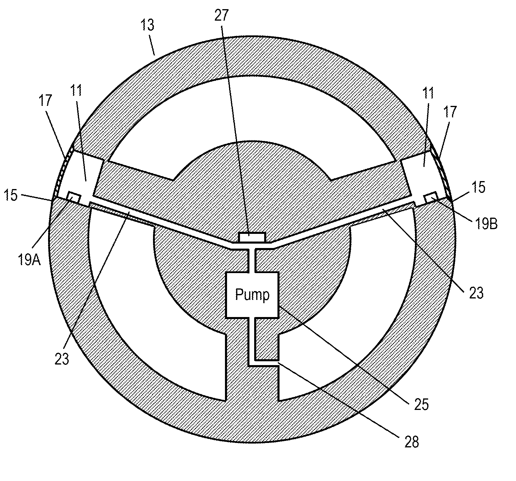
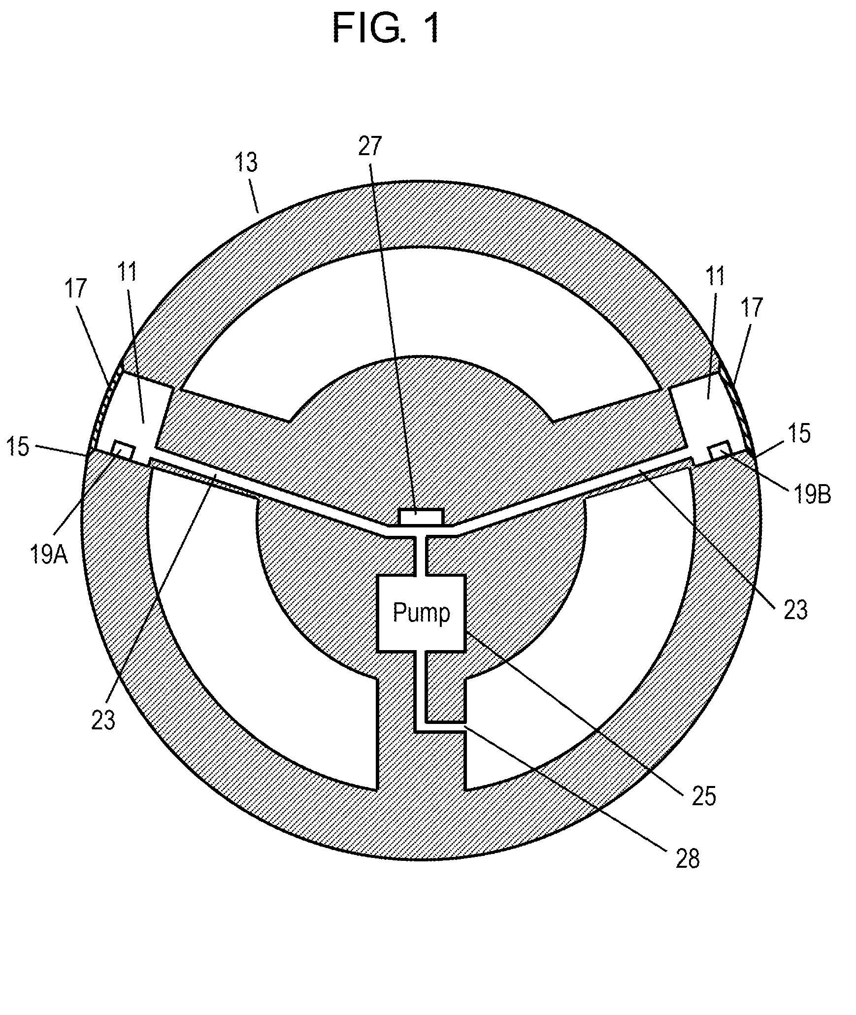
FIG. 1 is a schematic sectional view of a drunk driving detection system in accordance with a first exemplary embodiment of the present invention. FIGS. 2A through 2C are plan views showing configurations of pairs of contact detection electrodes in the drunk driving detection system. FIG. 3 is a block circuit diagram of the drunk driving detection system of FIG. 1. FIG. 4, FIG. 5, and FIG. 6 are an exploded perspective view, a perspective view, and a sectional view, respectively, of an alcohol sensor in the drunk driving detection system. FIG. 7 is a flowchart showing the operation of the drunk driving detection system of FIG. 1. FIG. 8, FIG. 9, and FIG. 10 are schematic sectional views of other structures of the drunk driving detection system in accordance with this exemplary embodiment.

This drunk driving detection system is to be incorporated into a motor vehicle. The drunk driving detection system includes steering wheel 13, films 17, a pair of first contact detection electrodes ...

second exemplary embodiment

FIG. 11 is a schematic sectional view of a drunk driving detection system in accordance with a second exemplary embodiment of the present invention. FIG. 12 is a block circuit diagram of the drunk driving detection system. FIG. 13 is a flowchart showing the operation of the drunk driving detection system. In the structure of the drunk driving detection system of the second embodiment, elements similar to those in the first embodiment have the same reference marks, and the detailed descriptions of those elements are omitted.

As shown in FIG. 11, the structure of this exemplary embodiment features that an alcohol sensor is formed of infrared light source (hereinafter “light source”) 51 and infrared sensor (hereinafter “sensor”) 53 both incorporated within steering wheel 13. Specifically, as shown by the dotted line in FIG. 11, an infrared ray generated from light source 51 repeatedly reflects in optical path 55 disposed along the circumferential direction of steering wheel 13 and reach...


PUM

PropertyMeasurementUnit
thicknessaaaaaaaaaa
temperatureaaaaaaaaaa
pulse currentaaaaaaaaaa

Abstract

A drunk driving detection system to be incorporated in a vehicle includes a steering wheel, a film, a pair of contact detection electrodes, an alcohol sensor, and a control circuit. The steering wheel is provided with an opening in a portion to be grasped by a driver. The film is liquid-impermeable and air-permeable, and covers the first opening. The contact detection electrodes are provided on the film. The alcohol sensor is provided in a space in communication with the opening. The control circuit is connected to the contact detection electrodes and the alcohol sensor, and measures the resistance between the contact detection electrodes. When the resistance is within a predetermined range, the control circuit determines that the driver is in contact with the film and detects an alcohol drinking condition of the driver based on the output from the alcohol sensor.

Description

BACKGROUNDThe present invention relates to an alcohol detection system to detect the level of alcohol consumed by a person. As one example, a drunk driving detection system is provided for a motor vehicle that detects mainly an alcohol drinking condition of the driver.In recent years, a drunk driving detection system for detecting an alcohol drinking condition of a driver has been developed to reduce the number of accidents caused by drunk driving. Further, studies are made on various systems for controlling the start and operation of a motor vehicle (hereinafter referred to as “vehicle”) based on the output from the drunk driving detection system.In such a drunk driving detection system, an alcohol sensor detects a concentration of alcohol typically in exhalation. This system utilizes the proportionality between the alcohol concentration in the blood increased by alcohol-drinking and the alcohol concentration in the exhalation. Such types of systems are also used in crackdown of dr...

Claims


Application Information

Patent Timeline
Patent Type & Authority Patents(United States)
IPC IPC(8): G08B23/00A61B3/113A61B5/00A61B5/18B60K28/06G01N21/35G01N21/3504G01N27/02G01N27/04G01N27/12G01N33/98
CPCB60K28/063B60W40/09B62D1/046G01N33/4972B60W2040/0836B60W2540/24
Inventor SHOJI, RIHITOYUKAWA, JUNICHIKONNO, FUMIYASUISHIZAKI, TOSHIO
Owner PANASONIC CORP
Why Eureka
Try Eureka