
Acoustic doppler dual current profiler system and method

a profiler and dual current technology, applied in the direction of volume measurement, liquid/fluent solid measurement, reradiation, etc., can solve the problems of difficult synchronization of data, low accuracy, and low accuracy, and achieve long profiling range, high power, and efficient operation

Active Publication Date: 2011-03-22
NORTEK
View PDF20 Cites 6 Cited by
  • Summary
  • Abstract
  • Description
  • Claims
  • Application Information

AI Technical Summary

Benefits of technology

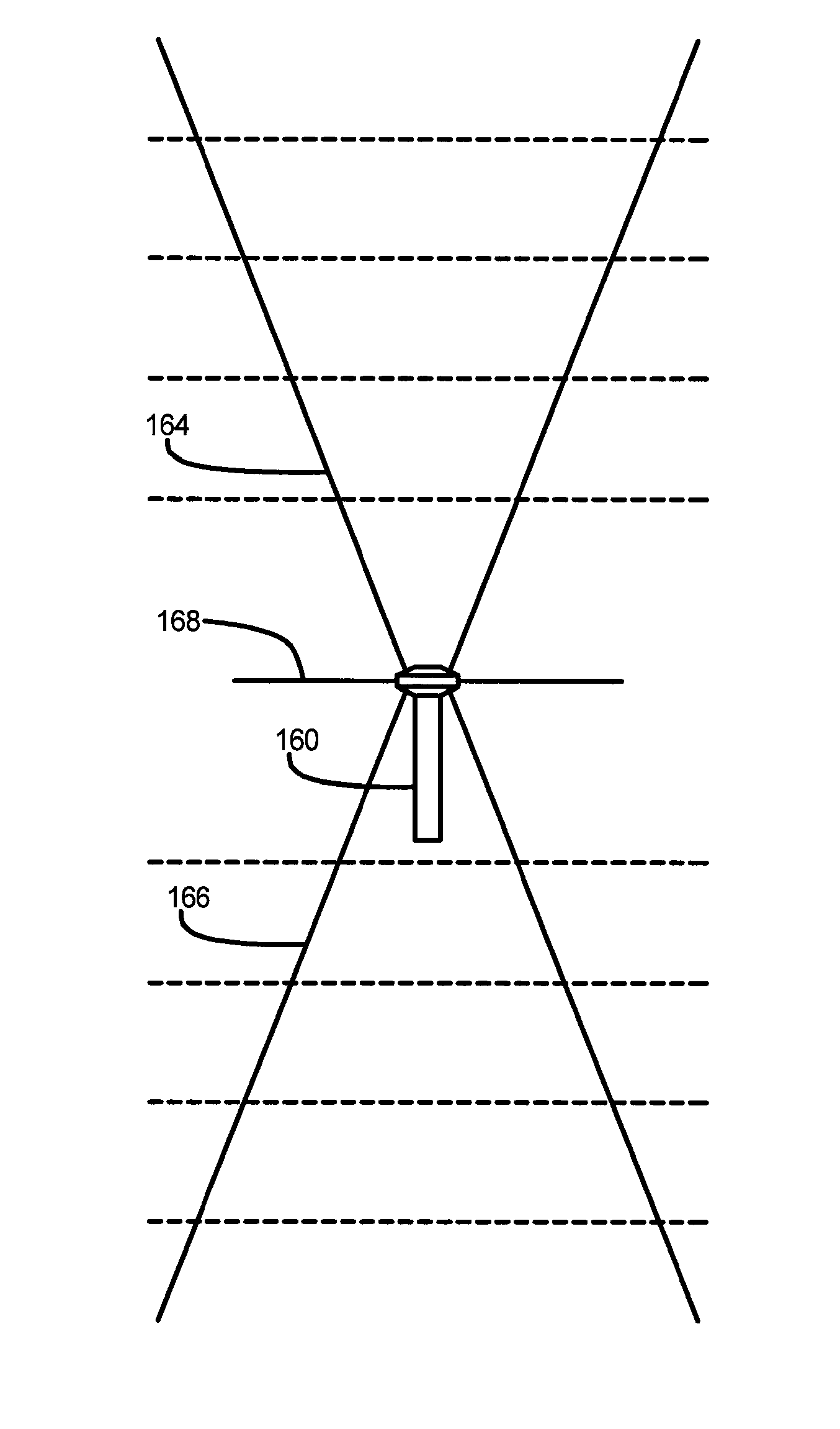
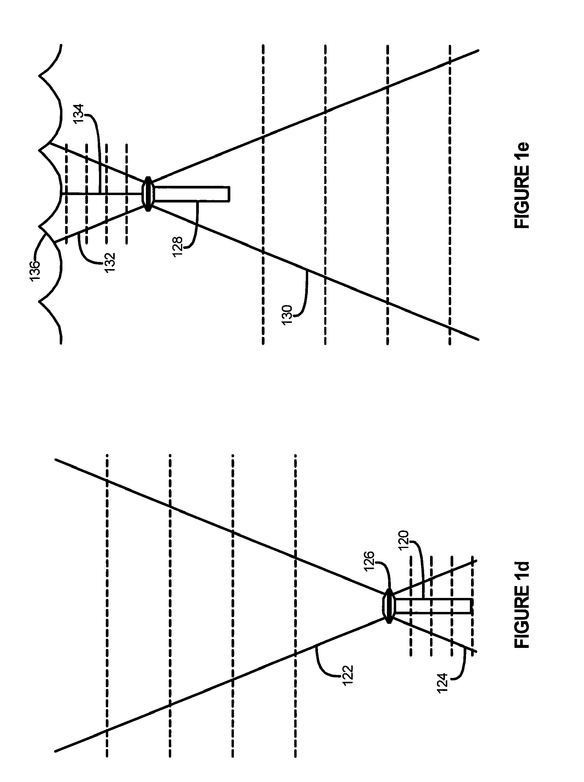
"The invention is a method and apparatus for observing multiple ocean processes simultaneously using a single instrument. The instrument has multiple beam sets with profiling catenations that are optimized for each process. The catenations are used to organize the data collected from each beam set separately, ensuring that each process has its own velocity profile. The instrument can make measurements at the scales of the process, from the surface to the deep sea. The use of multiple profiling catenations allows the instrument to capture the motions at the scales that characterize each process. The instrument can also make measurements at the depth of the instrument using horizontal beams, which doubles the profiling range and reduces the power needed for the vertical beams. The use of multiple beam sets facing upwards and downwards, or interleaving data from different beam sets, ensures that the data preserves the temporal relationships of the different processes. The instrument produces multiple beam sets that are precisely aligned with each other, making it easier to deploy and align the transducers. Overall, the invention provides a more efficient and effective way to observe ocean processes simultaneously."

Problems solved by technology

Current meters were spaced irregularly, they left gaps when they failed, and the drift of their internal clocks produced data that was difficult to synchronize.
Purely vertical beams can perform useful functions such as measuring the distance to the surface, but they do not provide information about the horizontal velocity.
However, as long as the tilting is not too large, the ADCP tilt has a relatively unimportant effect on the measurement quality and can be ignored.
An ADCP that uses higher power can measure velocity further from the ADCP, but it will then deplete its battery more quickly, therefore shortening the duration of the ADCP's deployment.
There are limits to the acoustic power that a transducer can actually get into the water, and the limits vary with frequency.
Longer transmit pulses reduce the velocity uncertainty, but also increase the size of depth cells.
As the distance from the ADCP increases, the acoustic signal / noise ratio falls to the point where the velocity data becomes too noisy to use.
ADCPs are able to compute and record velocity from beyond this range, but the data are not useful.
Users can optimize data collection for long range, for example, by maximizing power, using long transmit pulses, long depth cells, and large blanking, but maximizing the profiling range can also impair the ability of the ADCP to measure velocity close to the ADCP.
Scientists use the Navier-Stokes equations to model these processes, but the equation is too difficult to solve in general, so each process has its own particular simplifications and approximations that enable scientists to model and understand the process.
For example, a scientist studying the Gulf Stream would observe the bottom boundary layer under the Gulf Stream with a different ADCP because the scales are so different, but because the two ADCPs' clocks drift relative to one another, he would struggle when trying to compare the two data sets.

Method used


Image

  • Acoustic doppler dual current profiler system and method
  • Acoustic doppler dual current profiler system and method
  • Acoustic doppler dual current profiler system and method

Examples


Embodiment Construction

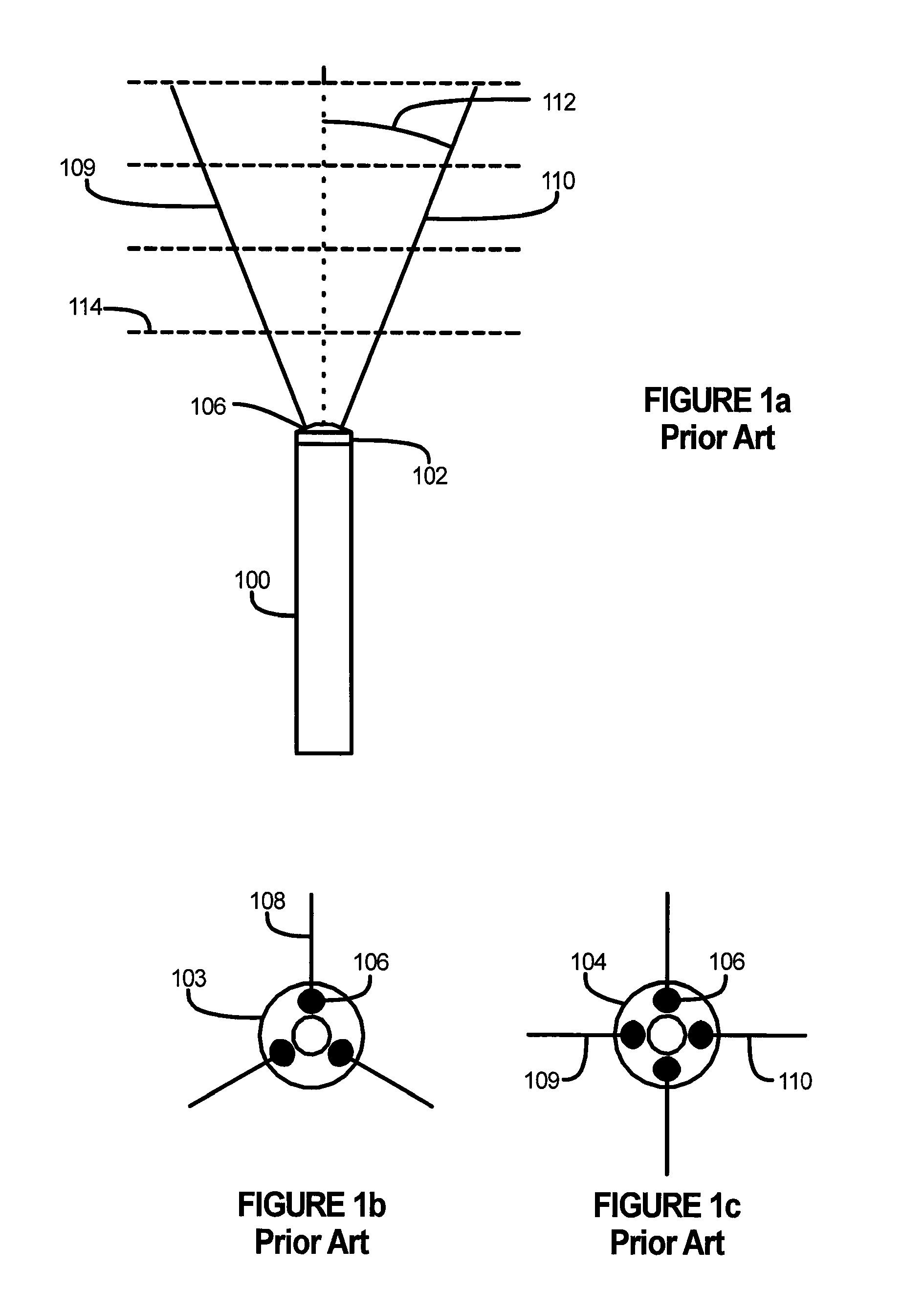
With reference initially to FIGS. 1a-1c, before describing an Acoustic Doppler Dual Current Profiler (“AD2CP”) in accordance with an embodiment of the present invention, some features of ADCPs of the prior art will first be described to assist the reader in understanding the invention.

With reference to FIG. 1a, an ADCP 100, shown in side view, has, at its top, a transducer assembly 102. This example illustrates an ADCP with its transducer assembly 102 facing upward, but the ADCP 100 could as easily be turned around to face downward. FIG. 1b shows the face of a transducer assembly 103 with three transducers 106, and FIG. 1c shows a transducer assembly 104 with four transducers 106. Each transducer 106 produces a corresponding beam 108, 109, and 110 of sound. The beam angle 112 (FIG. 1a) is the angle between the beam and vertical. This angle 112 is not the only angle required to define the direction of the beam, but it is the angle most commonly specified for an ADCP. Usually, though ...


PUM


Abstract

An AD2CP includes at least one transducer assembly emitting sets of slanted directional acoustic beams and receiving the echoes; and electronics that processes the echoes into depth cells and computes velocity in each depth cell. The AD2CP is configured so that each beam set has a profiling catenation, at least two of which are different, and the AD2CP is configured so that the emitting, receiving and processing operate contemporaneously.

Description

FIELD OF THE INVENTIONThe present invention relates generally to instruments and methods for measuring the velocity of water in the ocean.BACKGROUND OF THE INVENTIONAcoustic Doppler Current Profilers, or ADCPs, were first introduced and used by oceanographers in the late 1970s. ADCPs use acoustic beams to measure ocean current velocity over vertical profiles with ranges of a few meters to around 1000 m. They transmit sound, receive the echoes and process the echoes to detect changes in frequency associated with Doppler shifts produced by the relative velocity of the water and the ADCP. The result is a velocity profile, or velocity measurements in a series of depth cells forming a profile over depth. The ADCP either records the velocity profile data on an internal recorder or transmits the data to an external device or computer.Starting in the 1970s, ADCPs initiated a revolutionary change for people who studied the ocean. A single ADCP could replace the velocity measurements of a str...

Claims


Application Information

Patent Timeline
Patent Type & Authority Patents(United States)
IPC IPC(8): G01S15/00G01F1/66
CPCG01S7/523G01S15/582G01S15/588G01S15/88
Inventor LOHRMANN, ATLEGORDON, R. LEENYLUND, SVEN
Owner NORTEK
Learn More