Monitoring device for pitch systems of wind energy systems

a technology of monitoring device and wind energy system, which is applied in the direction of electric generator control, instruments, machines/engines, etc., can solve the problems of wear and tear of parts that are subject to the same disadvantage, and achieve the effects of reducing the complexity of hardware, reducing the burden, and reducing the burden

Active Publication Date: 2011-07-28
SIEMENS GAMESA RENEWABLE ENERGY SERVICE GMBH
View PDF13 Cites 40 Cited by
  • Summary
  • Abstract
  • Description
  • Claims
  • Application Information

AI Technical Summary

Benefits of technology

[0020]According to a further advantageous embodiment of the invention, which may be used for independent protection, a test control module is provided. This is designed to apply a selectable test characteristic to the actuating drive. For this purpose, the test control module has a memory with a plurality of test control characteristics, one of which is selected, and is used for testing by means of the load control module. At least three test characteristics are preferably contained as profiles in the memory. A first profile, which forms a load with a fixed resistance, a second profile, which forms a load with a constant current, and a third profile, which forms a load with a constant power. The load with a resistance forms the simplest case, which requires the least hardware complexity. The load with a constant power offers the advantage that it corresponds best to the load during actual operation. The load with a constant current offers the advantage that it produces the results which can be evaluated best, since the voltage changes of the battery when loaded can be used directly as a measure. In this case, the actuating drive is operated such that a constant current is passed through the motor. In this case, the actuating drive, together with its converter, acts like a transformer for direct current, in which case the transformation ratio can be varied by the drive. This is generally done by the test control module controlling the actuating drive with a predeterminable modulation degree. This can be varied corresponding to the respectively desired load. The intrinsically fixed resistance of the actual motor thus becomes a variable resistance on the battery side. This results in two major advantages with a minimal amount of additional hardware complexity, specifically on the one hand that the load on the battery can be changed and adjusted variably, and on the other hand that it is easily possible to compensate for other changes in the motor resistance, for example in the steady state as a result of scatters between individual motors, or dynamically as a result of a resistance increase because of heating. The test control module is expediently designed such that it detects actual parameters of the motor and has a compensation unit, which compensates for changes in the parameters from a standard value.
[0021]Compound motors, which have a series winding and a shunt winding, are preferably used as actuating drives in relatively large wind energy installations. It has been found that operation as a pure series-wound motor is better for the load test. The test control module expediently interacts with an excitation switching module which passes current only through the series winding, and disconnects the shunt winding, during the test.
[0022]In order to manage with as little additional load as possible on the components of the actuating drive, a direction selection module is preferably provided. This is designed to determine a load direction on the rotor blade during operation of the wind energy installation, and to act on the test control module such that the actuating drive operates the blade in the opposite direction. This advantageously makes use of the initial load on the blade caused by aerodynamic forces as an additional load, such that this relieves the load on the actuating drive and on the brake.

Problems solved by technology

Absolutely independently of the precise design used for the rechargeable batteries, they are nevertheless subject to the same disadvantage that these are parts which are subject to wear.

Method used


Image

  • Monitoring device for pitch systems of wind energy systems
  • Monitoring device for pitch systems of wind energy systems
  • Monitoring device for pitch systems of wind energy systems

Examples


Embodiment Construction

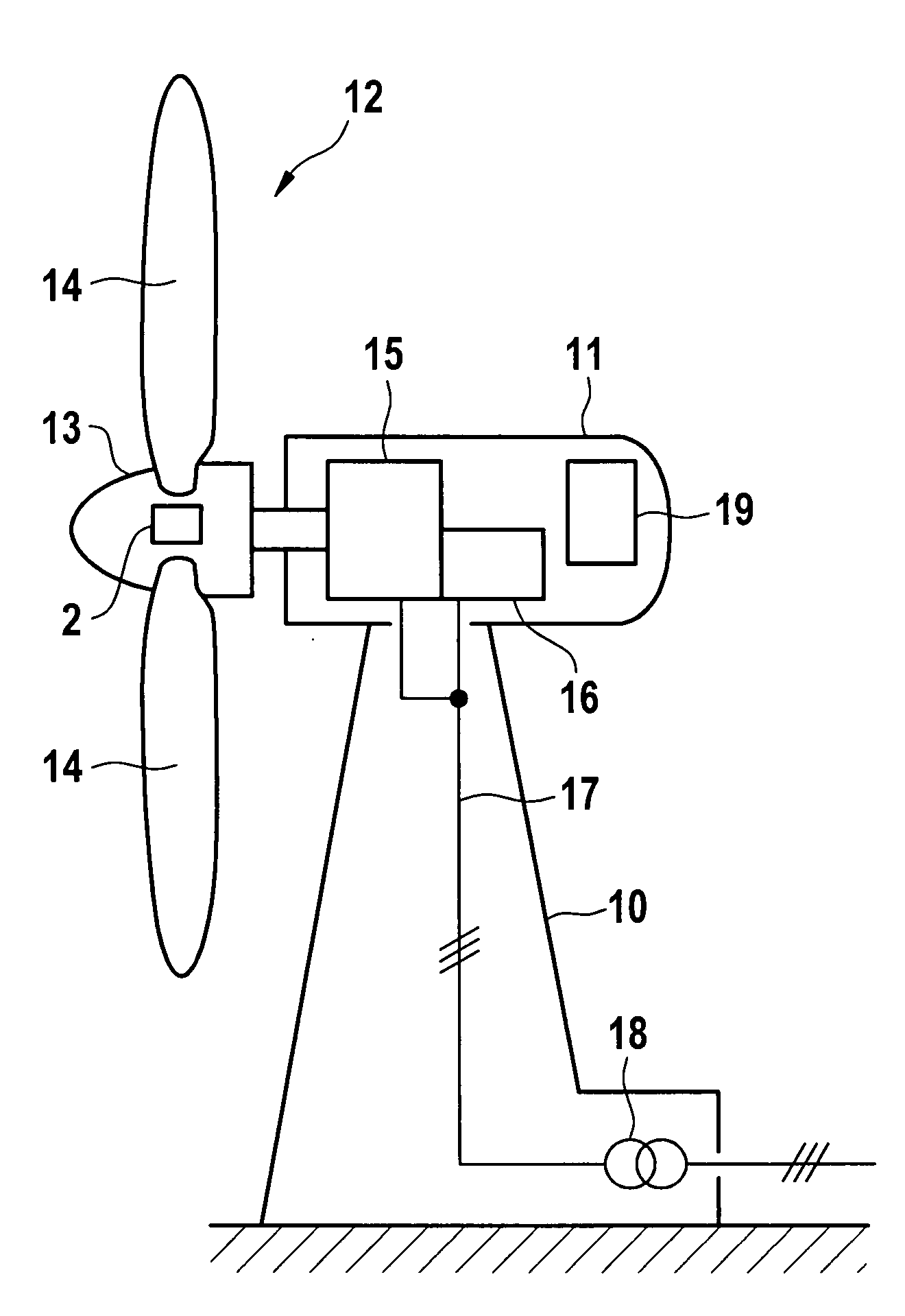
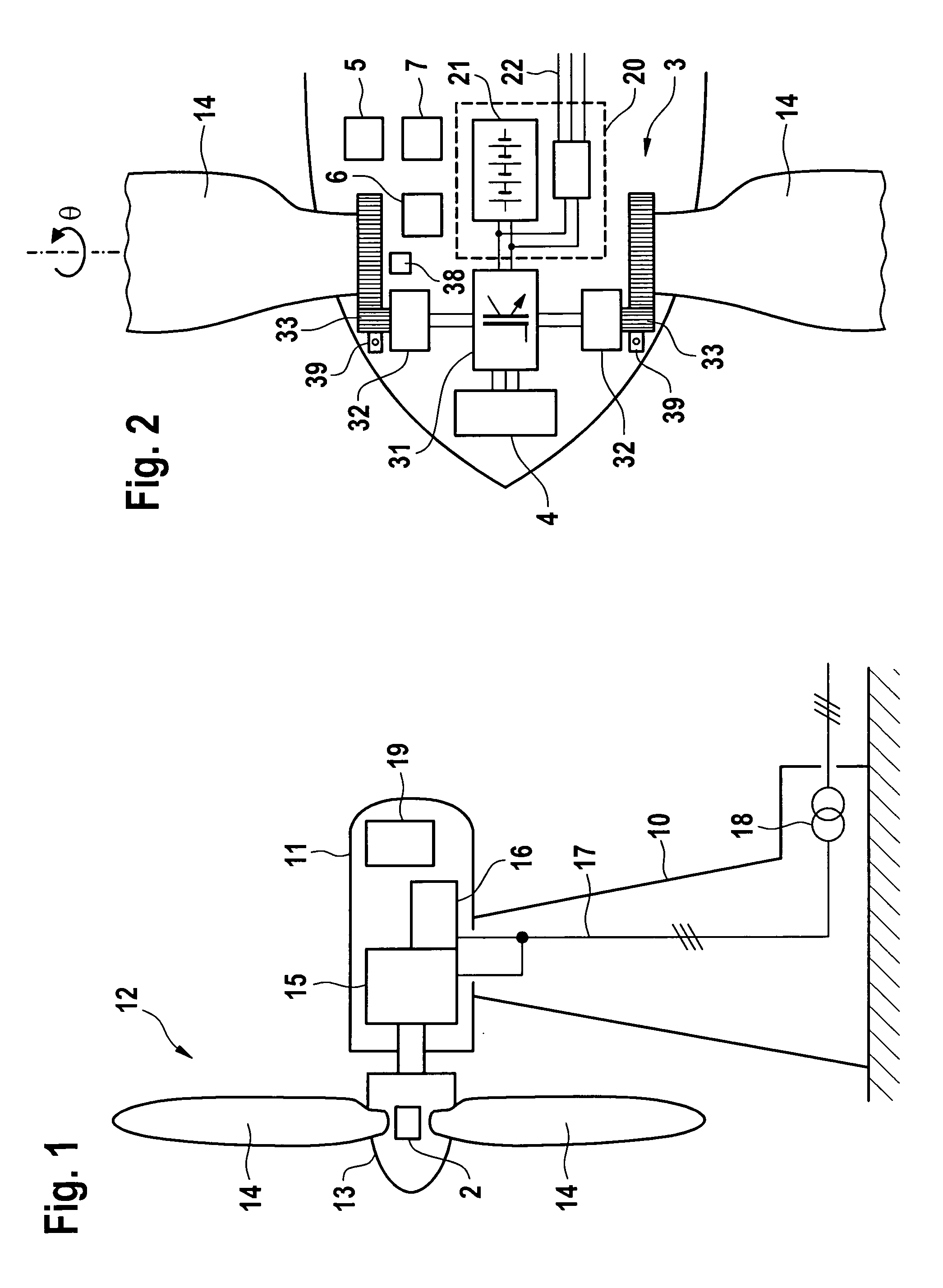
[0033]According to one exemplary embodiment of the invention, a wind energy installation has a pod 11, which can be pivoted in the azimuth direction on a tower 10 and on whose end face a wind rotor 12 is arranged such that it can rotate. The wind rotor 12 has a hub 13 and one or more rotor blades 14. It drives a generator 15 via a rotor shaft (which is not illustrated). This generator converts the mechanical power produced from the wind by the wind rotor 12 to electrical power. The generator 15 is a doubly-fed asynchronous machine (however, it is also possible to provide other types of generator). This generator 15 is connected to a converter 16. A line 17 is connected to the generator 15 and to the converter 16, and transports the electrical power that has been produced through the tower 10 to a medium-voltage transformer 18, which is arranged at the foot of the tower 10, for passing on into a power supply system (not illustrated). An operating control system 19 is also arranged in...


PUM


Abstract

A wind energy installation, monitoring device, and method. An exemplary wind energy installation includes a rotor including at least one blade and a generator configured to be driven by the rotor to produce electrical energy. The installation also includes a pitch device configured to vary the at least one blade of the rotor. The pitch device includes a power supply unit with a battery, an actuating drive, a monitoring unit, and a load module configured to switch the actuating drive between an operating mode and a test mode. In the test mode, the actuating drive forms a preselectable defined load for the battery. Accordingly, a high and reproducible load not dependent upon environmental conditions may be applied to conduct a stress test, even during ongoing operation.

Description

REFERENCE TO RELATED APPLICATIONS[0001]This application is a national stage application under 35 USC 371 of International Application No. PCT / EP2009 / 003842, filed May 29, 2009, which claims the priority of German Patent Application No. 10 2008 025 944.6, filed May 30, 2008, the contents of which prior applications are incorporated herein by reference.FIELD OF THE INVENTION[0002]The invention relates to a monitoring device for pitch systems for wind energy installations. To be more precise, the invention relates to wind energy installations having a rotor, a generator which is driven by the rotor in order to produce electrical energy, wherein the rotor has at least one blade which can be varied by means of a pitch device, wherein the pitch device has a power supply by means of a battery and has an actuating drive, and wherein a monitoring unit is provided for the battery for the pitch device.BACKGROUND OF THE INVENTION[0003]Wind energy installations of the type mentioned initially ha...

Claims


Application Information

Patent Timeline
Patent Type & Authority Applications(United States)
IPC IPC(8): H02P9/04
CPCF03D7/0224F05B2260/76F05B2260/80F05B2260/83Y02E10/723F05B2270/328F05B2270/504G01R31/343F05B2270/1074Y02E10/72
Inventor LETAS, HEINZ-HERMANNPETERS, MATTHIAS
Owner SIEMENS GAMESA RENEWABLE ENERGY SERVICE GMBH
Why Eureka
Try Eureka