Intelligent solid state relay/breaker

a solid-state relay and intelligent technology, applied in the direction of electrical devices, emergency protective arrangements for limiting excess voltage/current, and arrangements responsive to excess current, can solve the problems of high cost of mechanical relays, and large amount of power required to control coils. , to achieve the effect of reducing the component count and thus the pcb size, and high inrush curren

Inactive Publication Date: 2007-12-04
SHVARTSMAN VLADIMIR A
View PDF5 Cites 94 Cited by
  • Summary
  • Abstract
  • Description
  • Claims
  • Application Information

AI Technical Summary

Benefits of technology

[0015]The relay/breaker of the present invention is particular well suited for applications with a high inrush current. It can be used as a power distribution switch with capacitive a load, or inductive loads like motors, solenoids or the initial excess current of an incandescent lamp. It will switch all types of resistive, inductive and capacitive loads and acts as a microcontroller compatible power switch. By replacing ele

Problems solved by technology

These mechanical devices which are generally constructed with a coil and contacts have demonstrated considerable reliability although they suffer from problems associated with having moving parts.
In addition, mechanical relays are subject to arching and sparking.
In applications, where it is required to switch a high DC voltage, the cost of a mechanical relay grows very rapidly.
A lot of power is required to control the coil, and in high power relays, the coil can consume tens of watts.
Material fatigue can shorten the life of a mechanical relay, and reliability can suffer due to shock and vibration.
These types of mechanical issues are major concerns when the relay is used in harsh environments.
These relays are subject to constant vibrations introduced by

Method used


Image

  • Intelligent solid state relay/breaker
  • Intelligent solid state relay/breaker
  • Intelligent solid state relay/breaker

Examples


Embodiment Construction

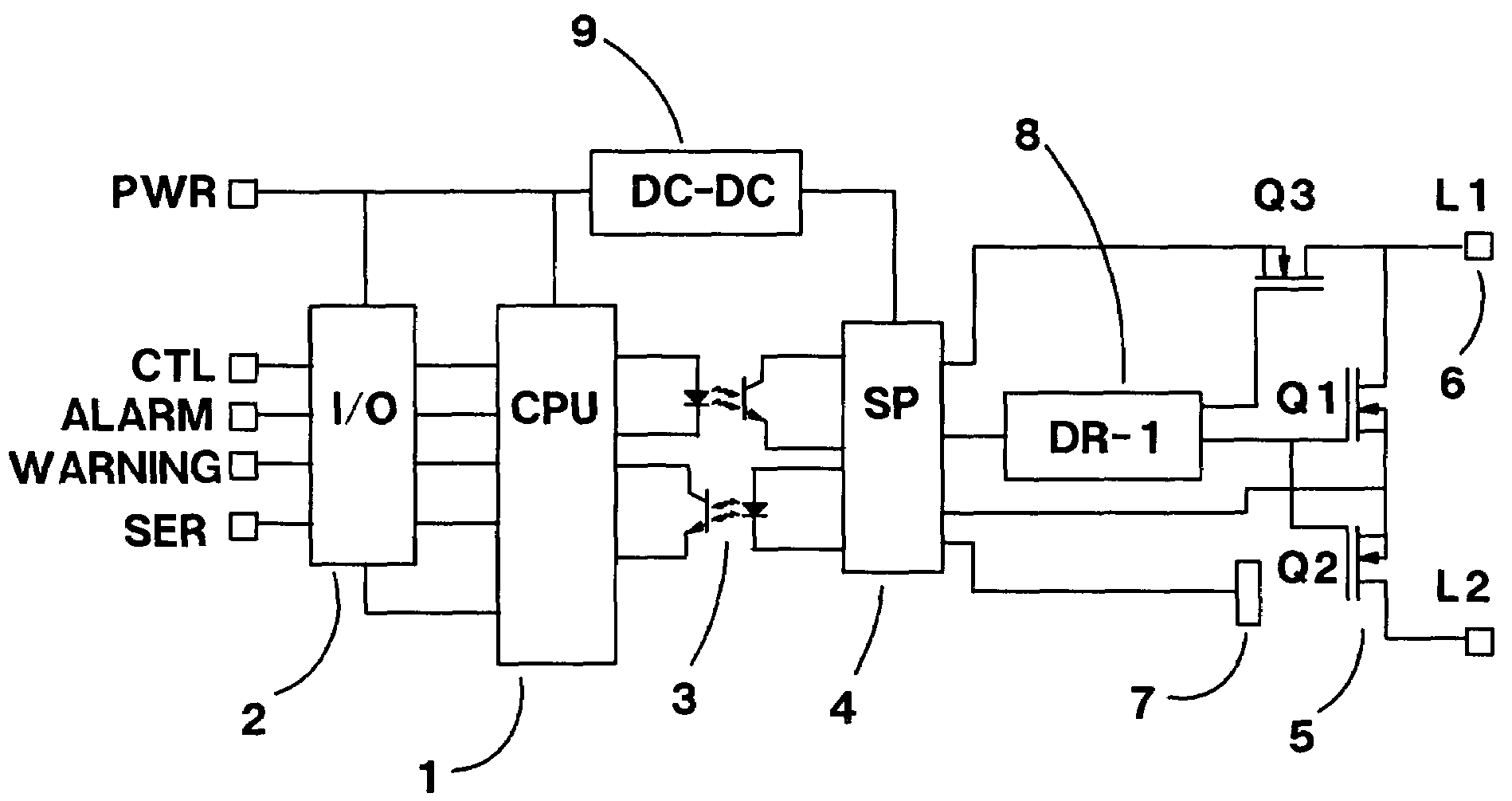
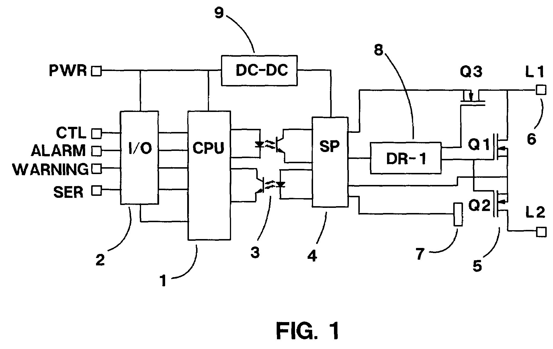
[0023]FIG. 1 shows a block diagram of an embodiment of the present invention. A CPU module 1 is coupled to an I / O interface 2 so that the device can be controlled and / or communicated with from an external microcontroller or microprocessor. The CPU 1 is shown to be isolated from the high power part of the device by means of optical couplers 3. While it is preferred to use isolation, it is possible to construct an embodiment of the present invention with no isolation. A pair of such optical couplers 3 can provide two-way communication between a signal processing module 4 and the CPU 1. Any number of optical channels is possible; however, two channels as shown in FIG. 1 can provide sufficient communication. In the preferred method, one of the optically channels 3 can provide an enable signal from the CPU 1, and the other can provide an alarm to the CPU 1.

[0024]It is also possible to provide more sophisticated communication between the CPU 1 and the signal processing module 4. In partic...


PUM


Abstract

A solid-state relay/breaker that can replace mechanical units to control any type of AC or DC load. Power MOSFETs or other transistors control a load current. A bypass current sensing path monitors MOSFET current and causes a shutdown through signal processing in the event of an over-current condition. This shutdown resembles that of a slow-blow fuse where the rate of shutdown is proportional to the value of the current. This prevents shutdown on momentary spikes or in-rush. In addition, temperature and internal power supply voltages are monitored to determine additional operational conditions where over-temperature or voltages out of range can also cause shutdown. The MOSFET and current sensing path are turned on and off in staggered timing with different slew rates to provide built-in hysteresis. The device can be manufactured in any type of package to match any type of environment or existing replacement requirement.

Description

BACKGROUND[0001]1. Field of the Invention[0002]The present invention relates generally to the field of electrical relays and breakers and more particularly to AC / DC intelligent solid state relay / breaker devices with current / temperature sensing, time-delay overloads and over-current / over-temperature protection.[0003]2. Description of Related Art[0004]Electromechanical relays have been used in the past in a wide-variety of power control and electrical applications. These mechanical devices which are generally constructed with a coil and contacts have demonstrated considerable reliability although they suffer from problems associated with having moving parts. In addition, mechanical relays are subject to arching and sparking. In applications, where it is required to switch a high DC voltage, the cost of a mechanical relay grows very rapidly. Also, the switching of the coil leads to voltage spikes (a fly-back voltage.) A lot of power is required to control the coil, and in high power re...

Claims


Application Information

Patent Timeline
IPC IPC(8): H02H9/02
CPCH02H3/085H02H5/044
Inventor SHVARTSMAN, VLADIMIR A.
Owner SHVARTSMAN VLADIMIR A
Why Eureka
Try Eureka