
Method and apparatus for photographic measurement

a technology for applied in the field of measuring equipment and photographs, can solve the problems of less accurate results and inability to obtain accurate results, and achieve the effects of convenient and efficient operation, convenient and efficient, and high portability

Inactive Publication Date: 2011-03-22
MINOR PAUL
View PDF20 Cites 66 Cited by
  • Summary
  • Abstract
  • Description
  • Claims
  • Application Information

AI Technical Summary

Benefits of technology

[0024]There is a need for an inexpensive and highly portable equipment that enables the measurement of objects at a distance. One important use for such an invention is to measure the features on the exterior of a building without actually approaching the building. In the field of real estate sales one may wish, for example, to know the length of a balcony on the front of a building. If the balcony is inaccessible, it may be impossible to obtain an accurate measurement. From two or more measurements, one is able to determine the area of surfaces, as for instance the surface area of the exterior of a building when there is the need for calculating the amount of paint to purchase. On site measurements using standard tools such as tape measures or laser distance measures are useful to a point, but it is more convenient and efficient to be able to save information that can be referred to at a later time for measurements forgotten, overlooked, or not previously thought to be needed. The present invention provides the ability to easily, quickly and inexpensively obtain information concerning exterior or interior surfaces in a form enabling immediate determination of dimensions of any portion that is visible to a camera lens, and also enabling off-site reference for further measurements at a later time.

Problems solved by technology

If the balcony is inaccessible, it may be impossible to obtain an accurate measurement.
The camera is preferably mounted on a tripod, but less accurate results can be obtained when the camera is hand held and carefully manipulated.

Method used


Image

  • Method and apparatus for photographic measurement
  • Method and apparatus for photographic measurement
  • Method and apparatus for photographic measurement

Examples


Embodiment Construction

[0033]The above described drawing figures illustrate the described apparatus and its method of use in at least one of its preferred, best mode embodiment, which is further defined in detail in the following description. Those having ordinary skill in the art may be able to make alterations and modifications to what is described herein without departing from its spirit and scope. Therefore, it should be understood that what is illustrated is set forth only for the purposes of example and should not be taken as a limitation on the scope of the present apparatus and its method of use.

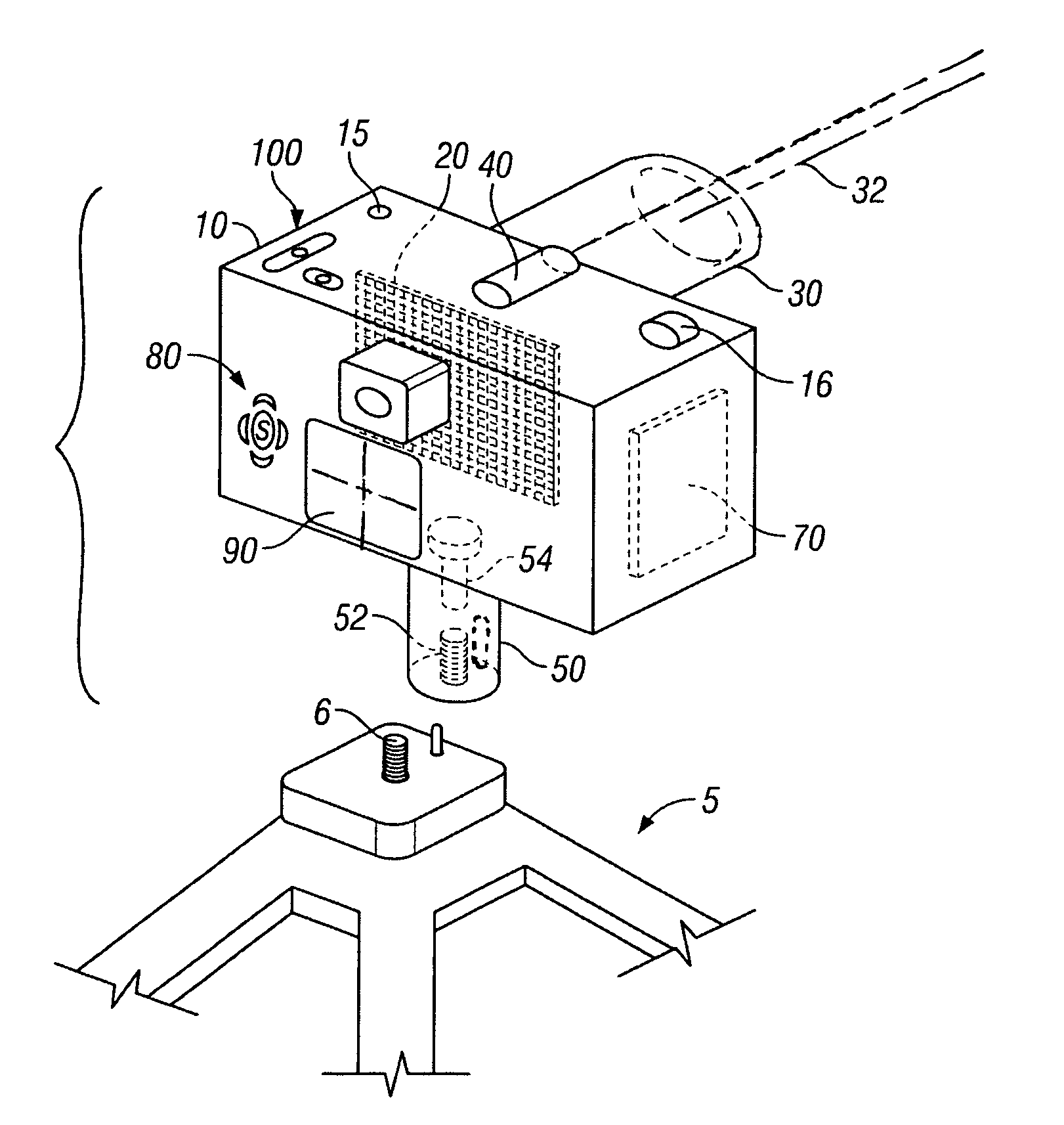
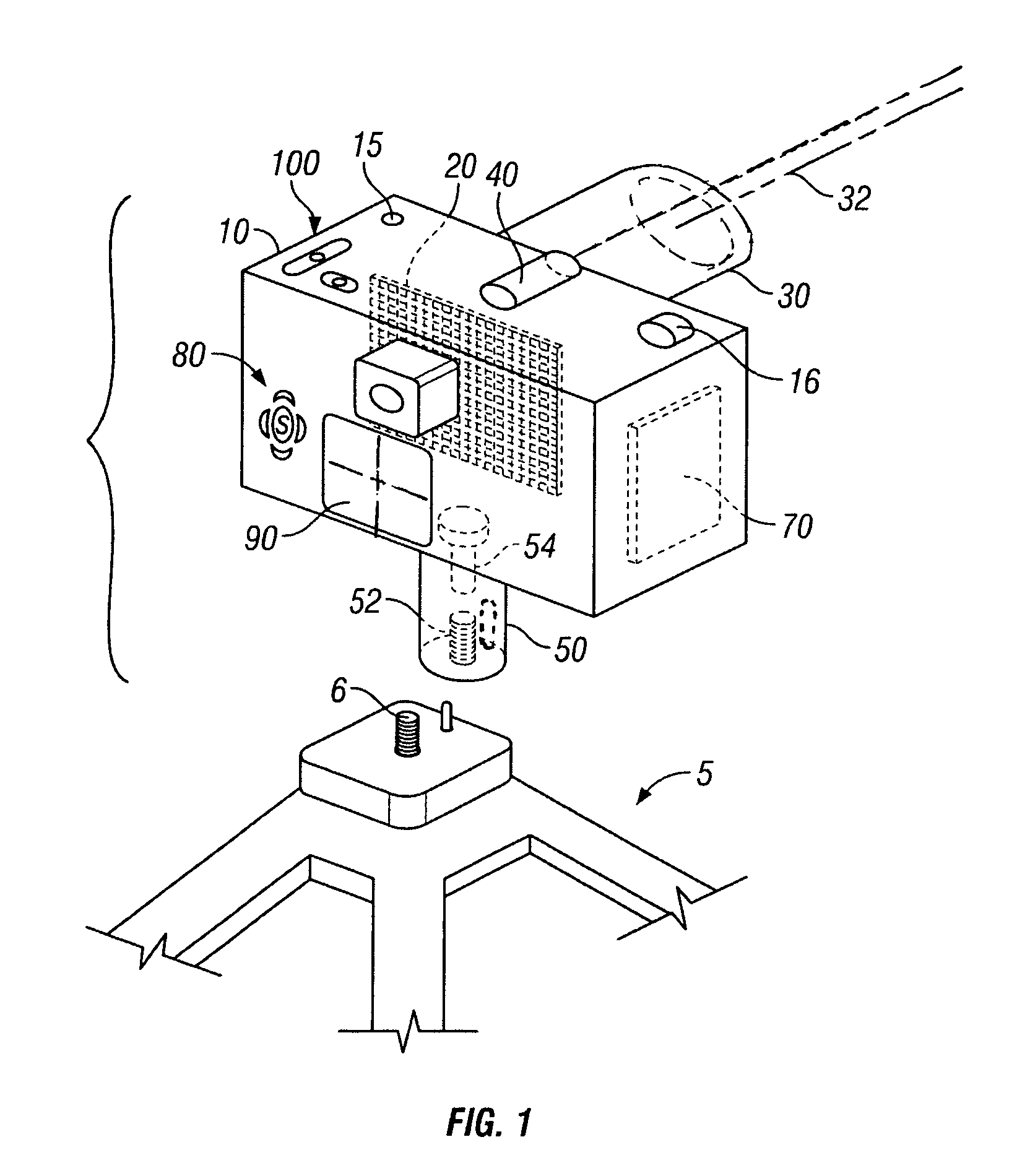
[0034]Referring to FIG. 1 we see that the present invention is a camera 10 which has a pixilated image receiver 20, and a telephoto lens 30, the lens enabled for alternately viewing a wide angle field of view and a narrow angle field of view. The lens 30 may also be continuously adjustable between the wide and narrow angles, and this is preferable. The telescopic range of the lens 30 is such that the wide ...


PUM


Abstract

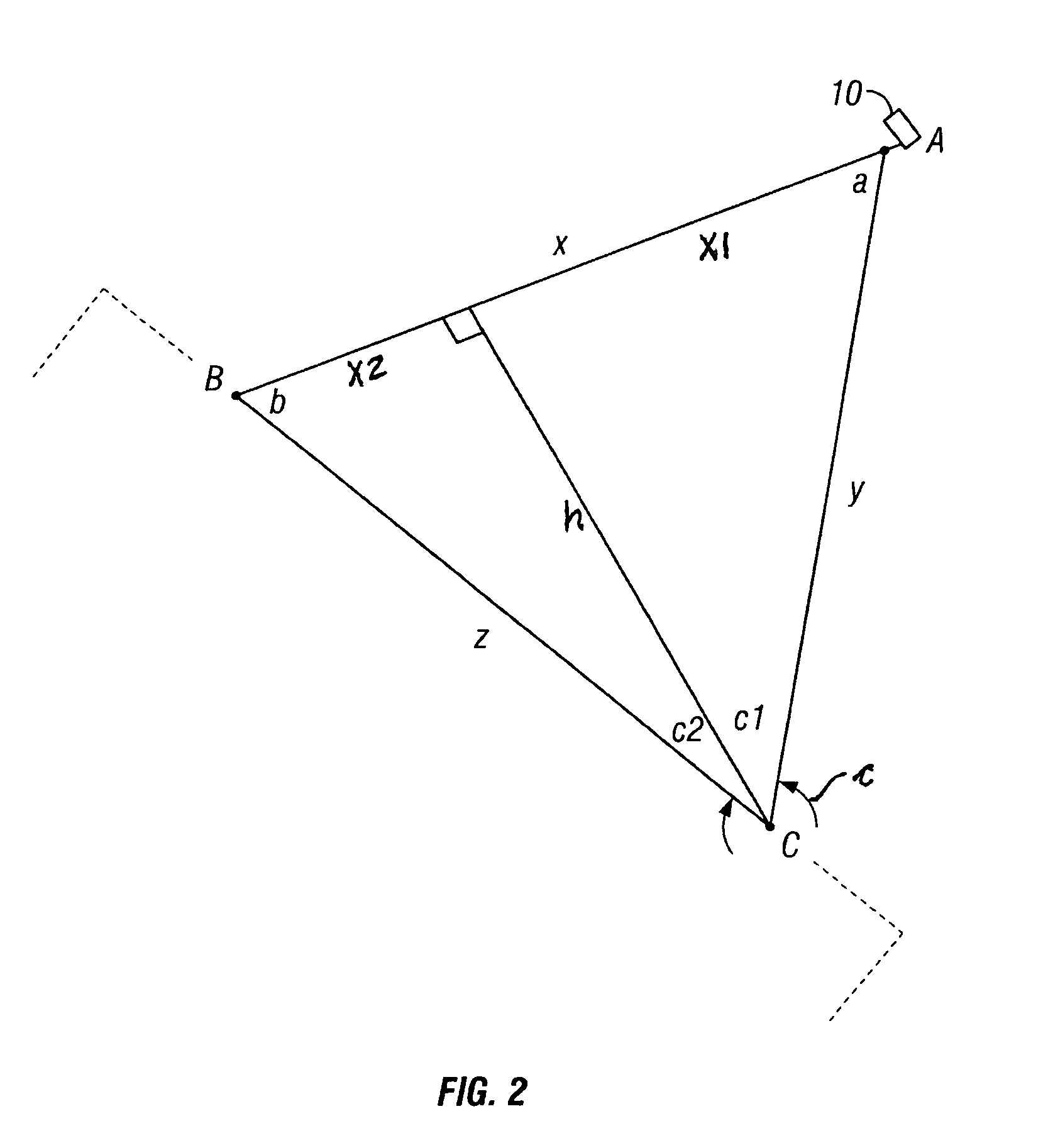
A camera is capable of measuring distances to objects in a photographic field of view and when two such distances are measured and the included angle between their paths, a measurement standard and a vertical plane are defined. The standard is then used to measure linear dimensions of any objects within the defined vertical plane and field of view. The camera, itself, can be used, on site, to measure various objects in the field of view, or the information may be transmitted for use off site use.

Description

CROSS-REFERENCE TO RELATED APPLICATIONS[0001]This is a Continuation-In-Part application of U.S. patent application Ser. No. 11 / 623,564, filed Jan. 16, 2007, which is incorporated herein by reference.BACKGROUND OF THE INVENTION[0002]1. Field of the Present Disclosure[0003]This disclosure relates generally to an apparatus and method for determining dimensions of objects using photographic technique.[0004]2. Description of Related Art Including Information Disclosed Under 37 CFR 1.97 and 1.98[0005]Kobayashi et al., US 20060187333 discloses an image pickup device which includes: image pickup means that opposes correctly to a photographic subject, and forms and picks up an image of the same; display means that displays an image data picked up by the image pickup means; distance measuring means that measures a distance to the photographic subject to be picked up by the image pickup means; index display means that displays an index on the display means so as to be superimposed on the image...

Claims


Application Information

Patent Timeline
Patent Type & Authority Patents(United States)
IPC IPC(8): G06K9/36
CPCG01B11/02G01C3/085G03B13/30G03B37/02H04N5/23212H04N23/671H04N23/50
Inventor MINOR, PAUL
Owner MINOR PAUL
Learn More