

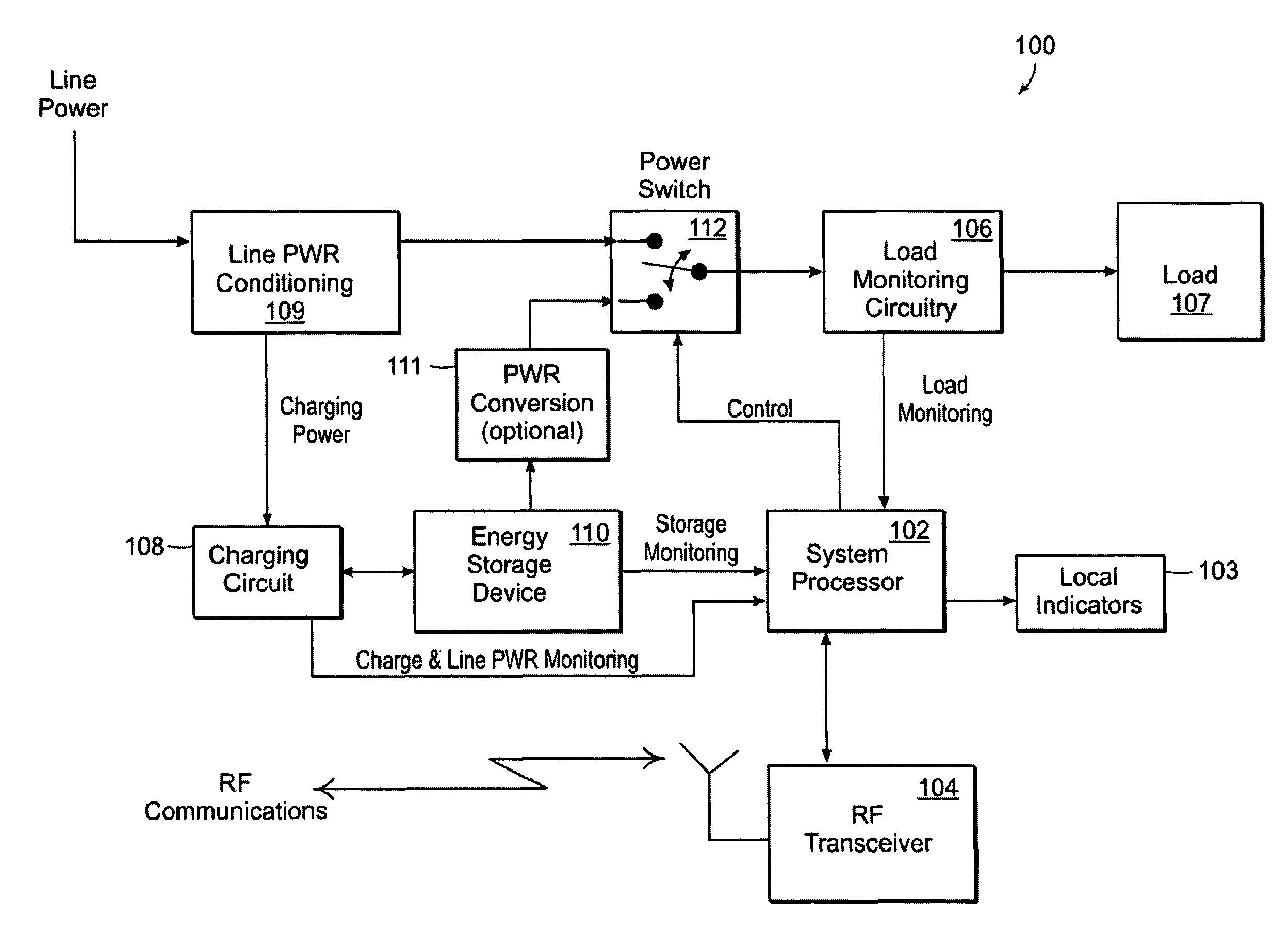
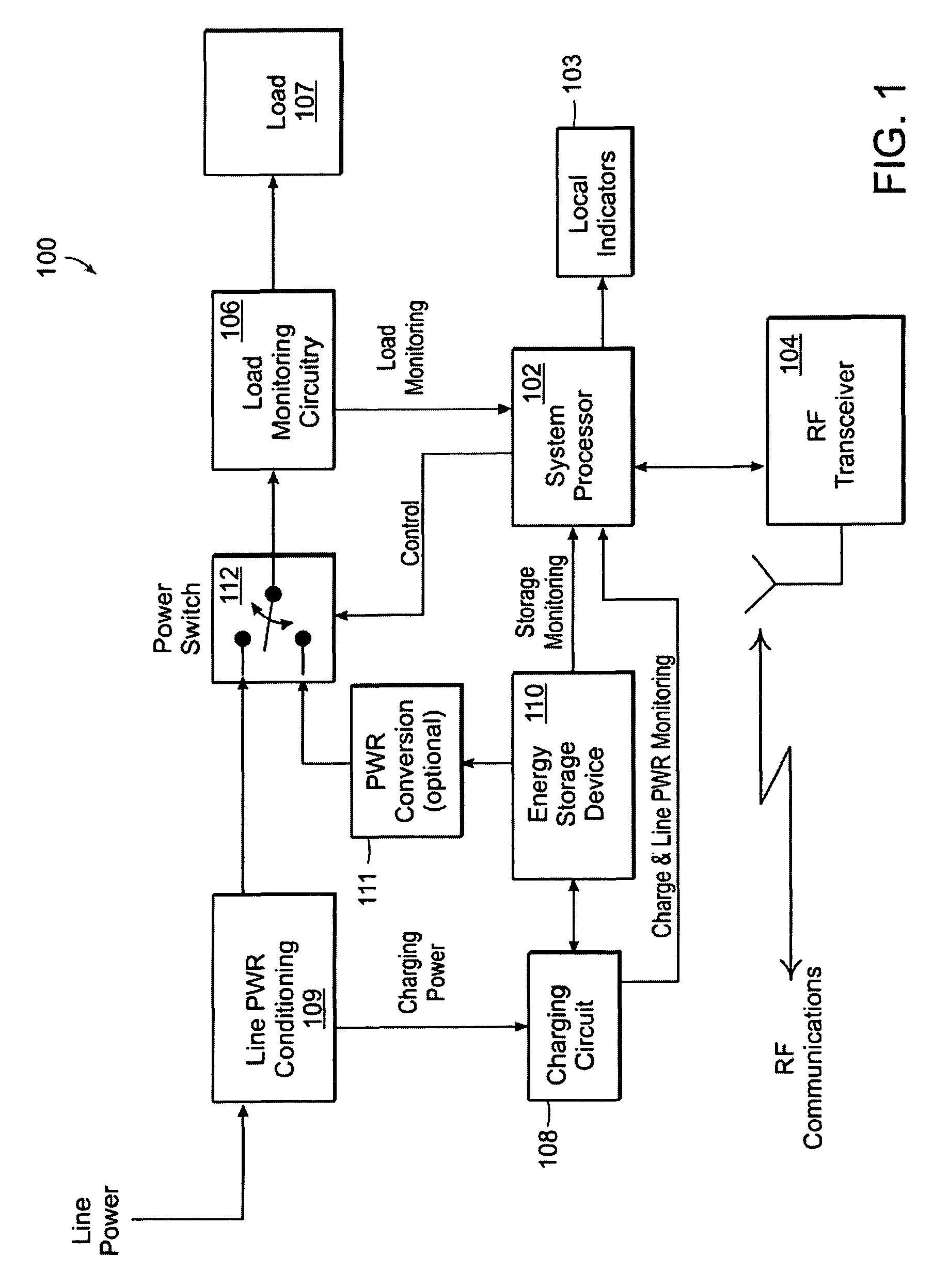
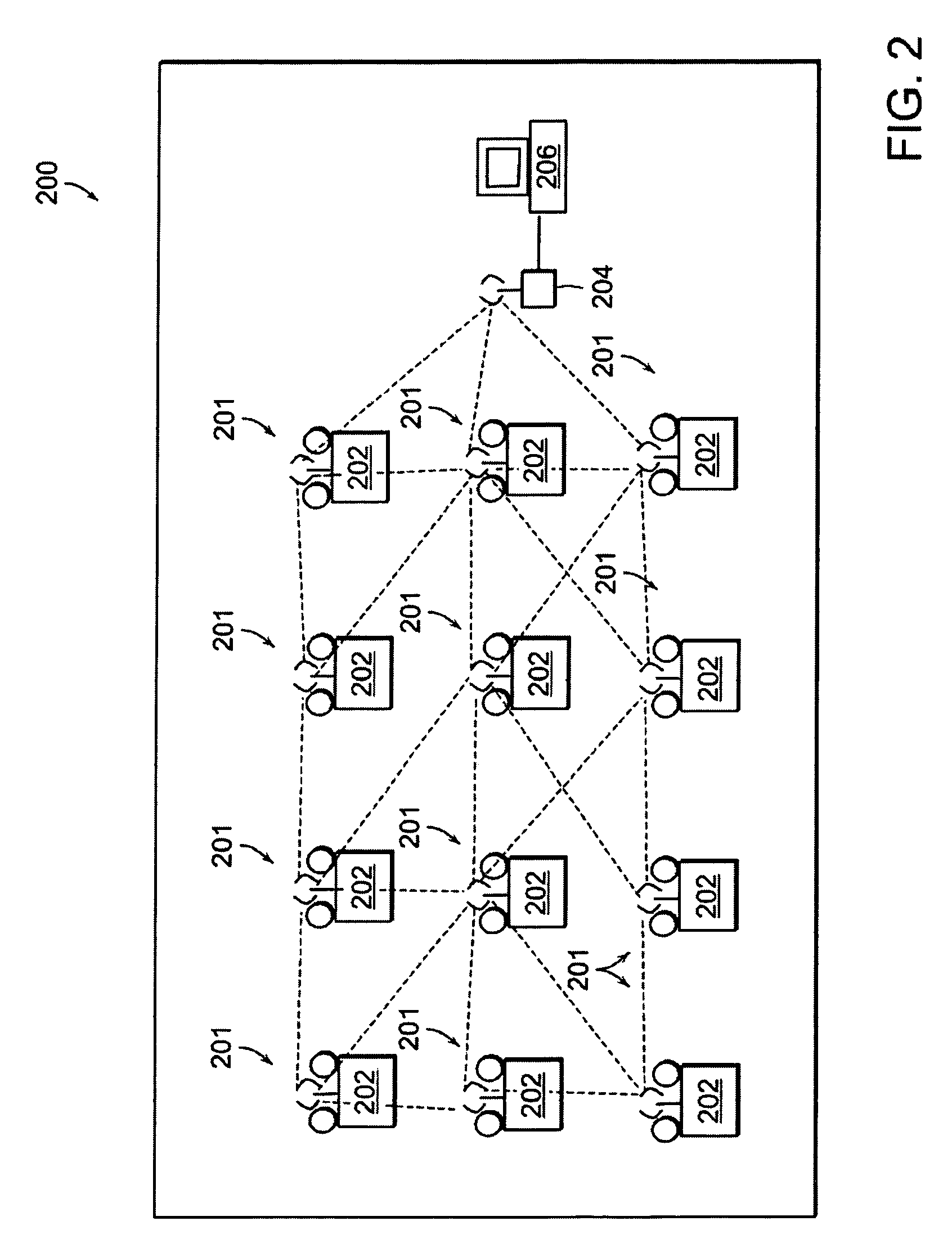
Remotely monitored and controlled distributed emergency power system
a power system and remote monitoring technology, applied in the direction of lights, alarms, instruments, etc., can solve the problems of laborious testing, inability to perform regular testing, and human error in testing in these known systems
- Summary
- Abstract
- Description
- Claims
- Application Information
AI Technical Summary
Problems solved by technology
Method used
Image

Examples
Embodiment Construction
[0011]Reference in the specification to “one embodiment” or “an embodiment” means that a particular feature, structure, or characteristic described in connection with the embodiment is included in at least one embodiment of the invention. The appearances of the phrase “in one embodiment” in various places in the specification are not necessarily all referring to the same embodiment.
[0012]While the present teachings are described in conjunction with various embodiments and examples, it is not intended that the present teachings be limited to such embodiments. On the contrary, the present teachings encompass various alternatives, modifications and equivalents, as will be appreciated by those of skill in the art. In particular, while some aspects of the present invention are described in connection with emergency lighting systems, it should be understood that the present invention can be used in connection with numerous types of distributed power units and distributed emergency power u...
PUM
 Abstract
Description
Claims
Application Information