
Device for reducing soot emissions in a vehicle combustion engine

a combustion engine and soot reduction technology, which is applied in the direction of combustion engines, machines/engines, pistons, etc., can solve the problems of high soot formation, poor mixing at high temperature, and loss of a lot of momentum, and achieve the effect of reducing soot emissions

Active Publication Date: 2011-04-05
VOLVO LASTVAGNAR AB
View PDF8 Cites 10 Cited by
  • Summary
  • Abstract
  • Description
  • Claims
  • Application Information

AI Technical Summary

Benefits of technology

[0001]The present invention relates to a device for controlling the combustion process in a combustion engine. The invention especially relates to such a device for reducing soot emissions in combustion engines in which the fuel / cylinder gas mixture is ignited by compression heat generated in the cylinder.

Problems solved by technology

The process is very complicated.
Combustion with fuel-heavy, i.e. rich, fuel / air mixture with poor mixing at high temperature produces high soot formation.
A lot of the momentum is lost when the spray plume hits the inner bowl floor section.

Method used


Image

  • Device for reducing soot emissions in a vehicle combustion engine
  • Device for reducing soot emissions in a vehicle combustion engine
  • Device for reducing soot emissions in a vehicle combustion engine

Examples


Embodiment Construction

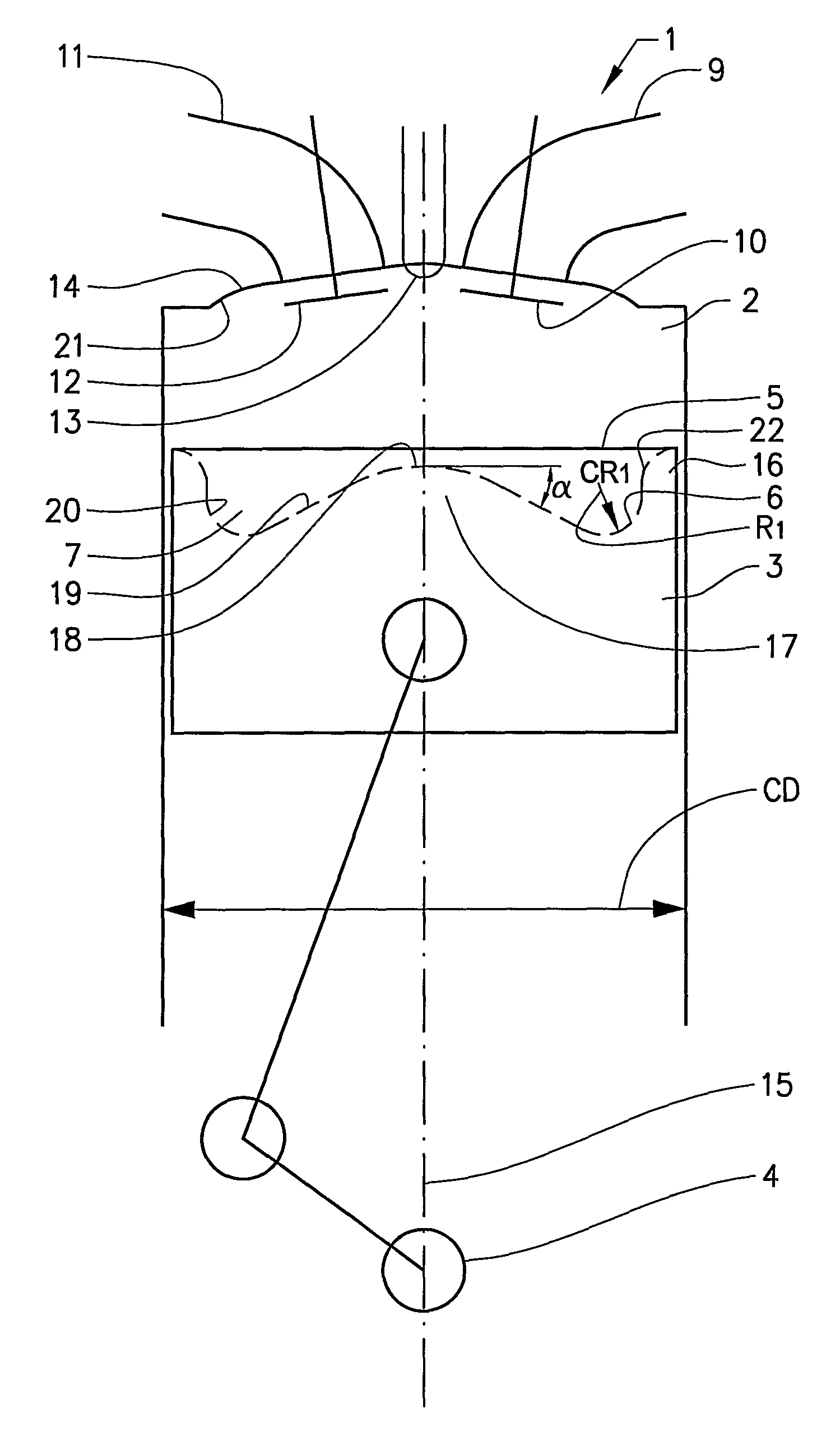
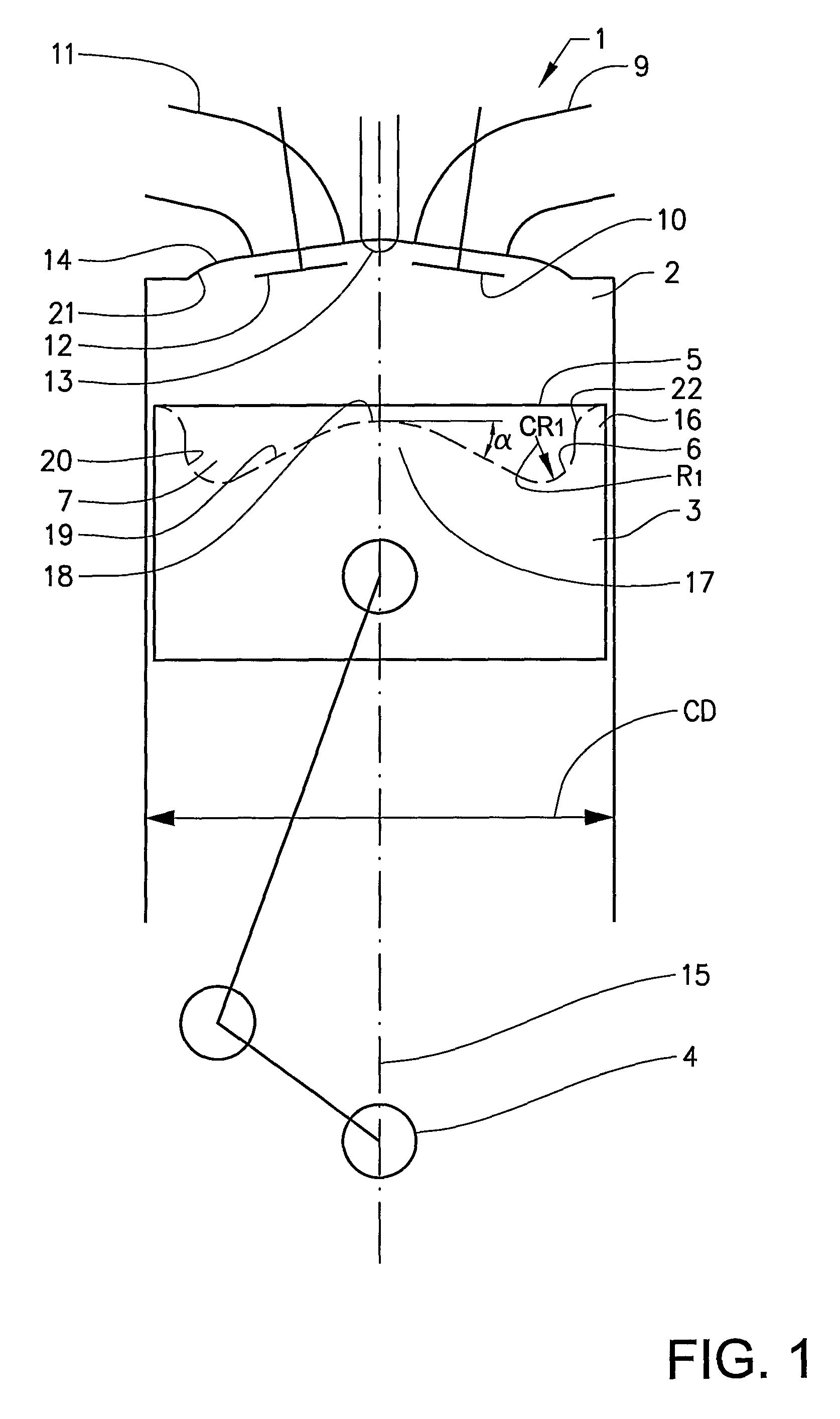
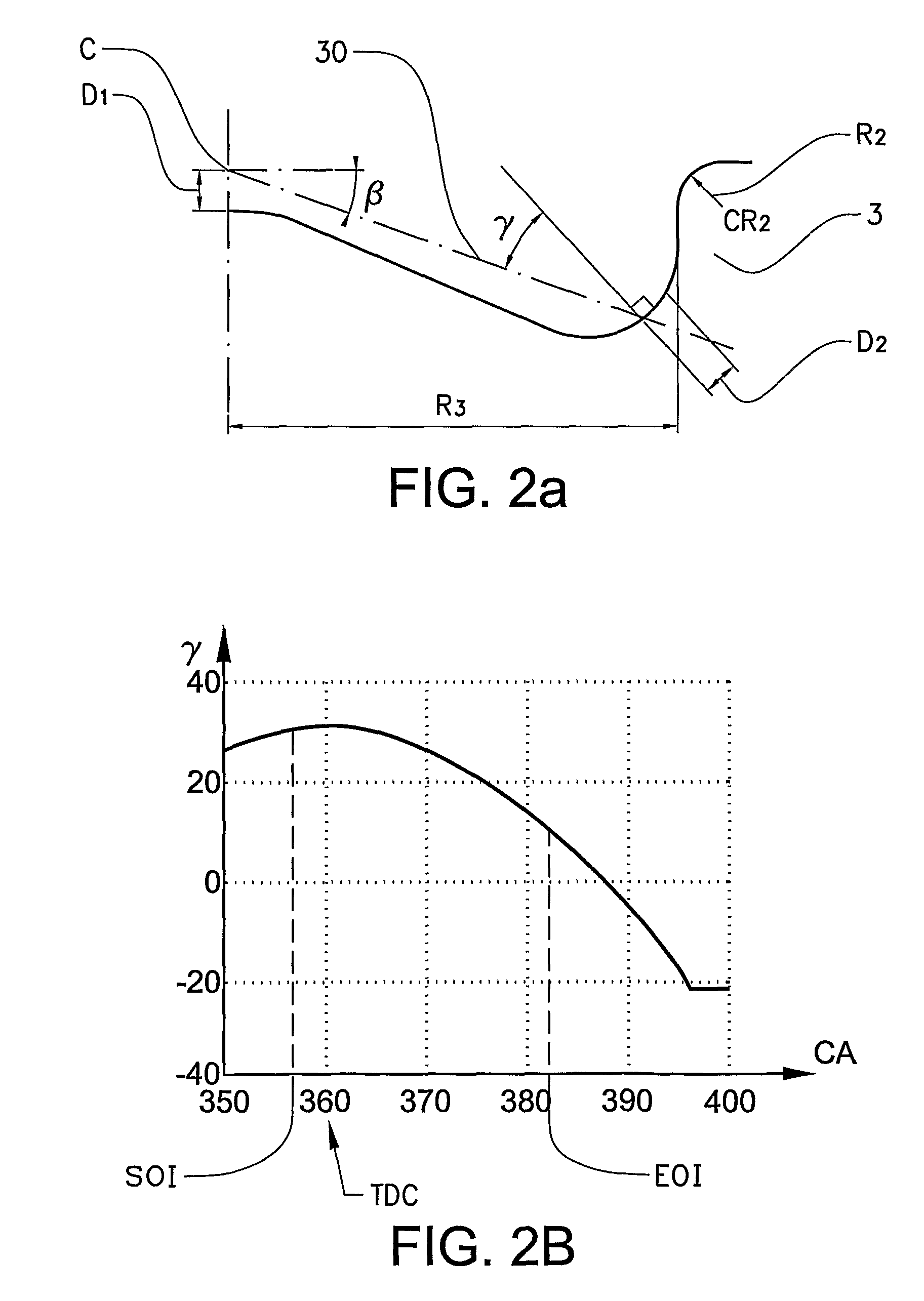
[0033]To understand the unique physical characteristics of combustion chamber 7 according to the invention, attention is initially directed to FIGS. 1 and 2a illustrating the various physical characteristics or parameters which are required to achieve the unexpected emission reduction advantages of the present invention.

[0034]In FIG. 1, a diagrammatic view is shown of a combustion engine 1 which is designed to work according to the diesel process. The engine 1 comprises a cylinder 2 and a piston 3, which reciprocates in the cylinder 2 and is connected to a crankshaft 4 so that the piston 3 is set to reverse in the cylinder 2 at an upper and lower dead centre position. As is also common, one end of the cylinder cavity is closed by a engine cylinder head 14. The piston 3 is provided in its upper surface 5 with a piston bowl 6, which forms a combustion chamber 7, together with inner surface 21 of a cylinder head 14 and walls of the cylinder 2. In the cylinder head 14 one or more induct...


PUM


Abstract

An internal combustion engine includes a combustion chamber, at least one intake port for directing intake air into the combustion chamber with no / low swirling; a piston with piston bowl, an injector with plurality of orifices arranged to inject fuel with high injection pressure to form spray plumes, each of the plurality of orifices having a central axis oriented at a positive spray angle sufficient to cause the spray / flame to impinge on a piston outer bowl section and a curvilinear shape of the outer bowl section is such that a reflection angle of the impingement of the central axis is positive during at least start of injection in order to increase balance between vertical upwardly directed and tangential movements of the spray / flame and to preserve mixing energy late in the combustion cycle for increased soot oxidation.

Description

BACKGROUND AND SUMMARY[0001]The present invention relates to a device for controlling the combustion process in a combustion engine. The invention especially relates to such a device for reducing soot emissions in combustion engines in which the fuel / cylinder gas mixture is ignited by compression heat generated in the cylinder.[0002]Soot particles (or particulates) are a product which, during combustion, can both be formed and subsequently oxidized into carbon dioxide (CO2). The quantity of soot particles measured in the exhaust gases is the net difference between formed soot and oxidized soot. The process is very complicated. Combustion with fuel-heavy, i.e. rich, fuel / air mixture with poor mixing at high temperature produces high soot formation. If the formed soot particles can be brought together with oxidizing substances such as oxygen atoms (0), oxygen molecules (O2), hydroxide (OH) at sufficiently high temperature for a good oxidation rate, then a greater part of the soot part...

Claims


Application Information

Patent Timeline
Patent Type & Authority Patents(United States)
IPC IPC(8): F02B3/00
CPCF02B23/0696Y02T10/125Y02T10/12
Inventor EISMARK, JANBALTHASAR, MICHAEL
Owner VOLVO LASTVAGNAR AB
Learn More