
Injector double row cluster configuration for reduced soot emissions

a cluster configuration and injection system technology, applied in the direction of fuel injector pumps, machines/engines, mechanical equipment, etc., can solve the problems of generally having a negative influence on soot emissions, and achieve the effects of optimizing cluster distribution, minimizing soot emissions, and maximizing soot oxidation

Inactive Publication Date: 2006-11-23
GM GLOBAL TECH OPERATIONS LLC
View PDF21 Cites 4 Cited by
  • Summary
  • Abstract
  • Description
  • Claims
  • Application Information

AI Technical Summary

Benefits of technology

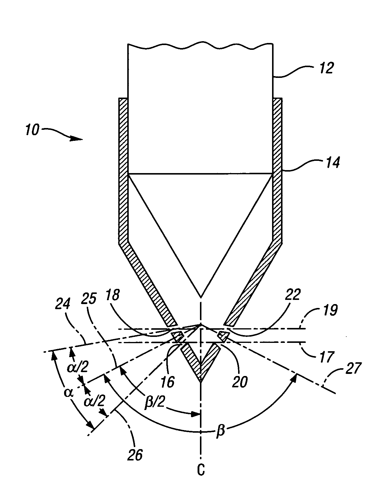
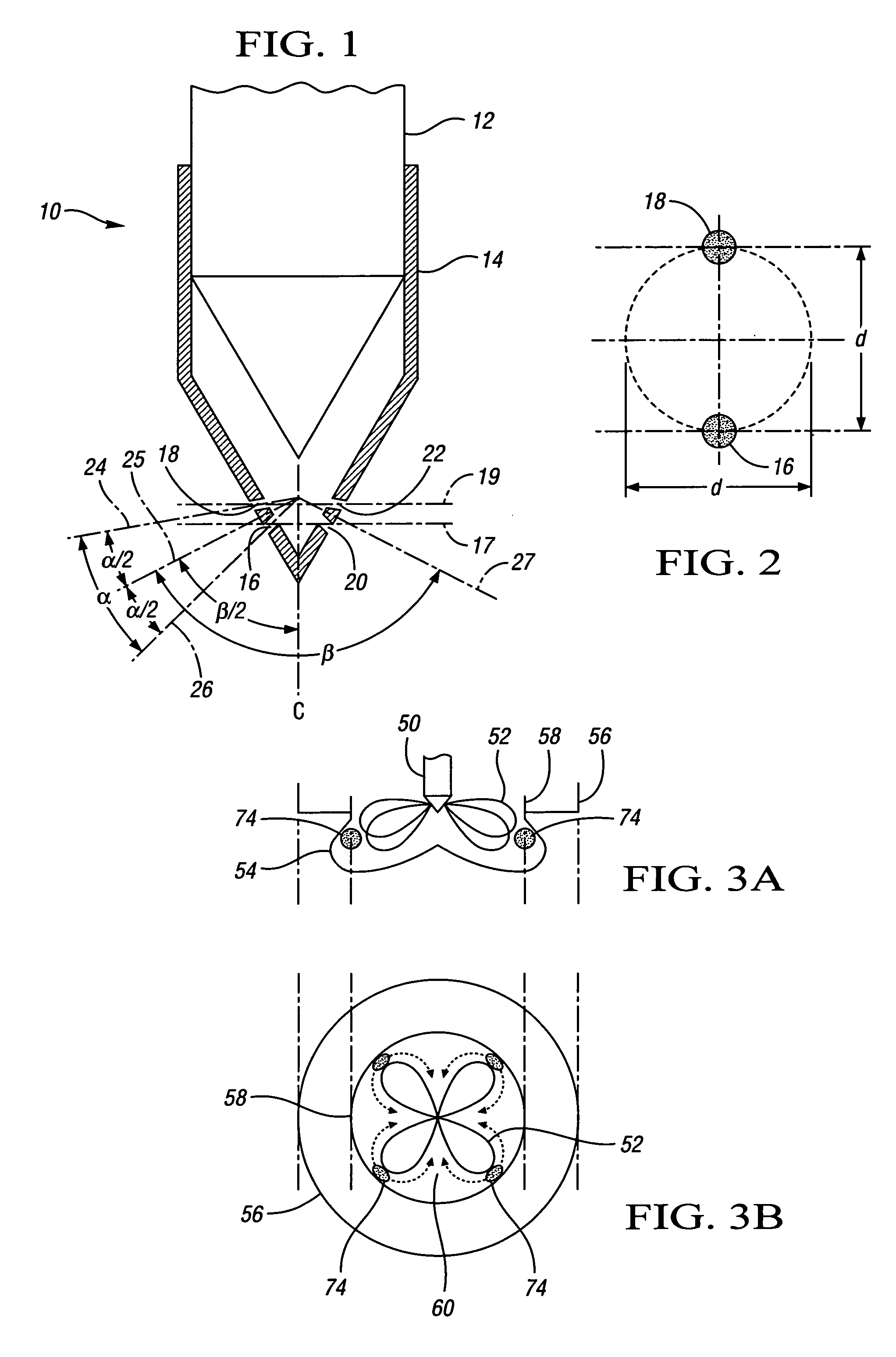
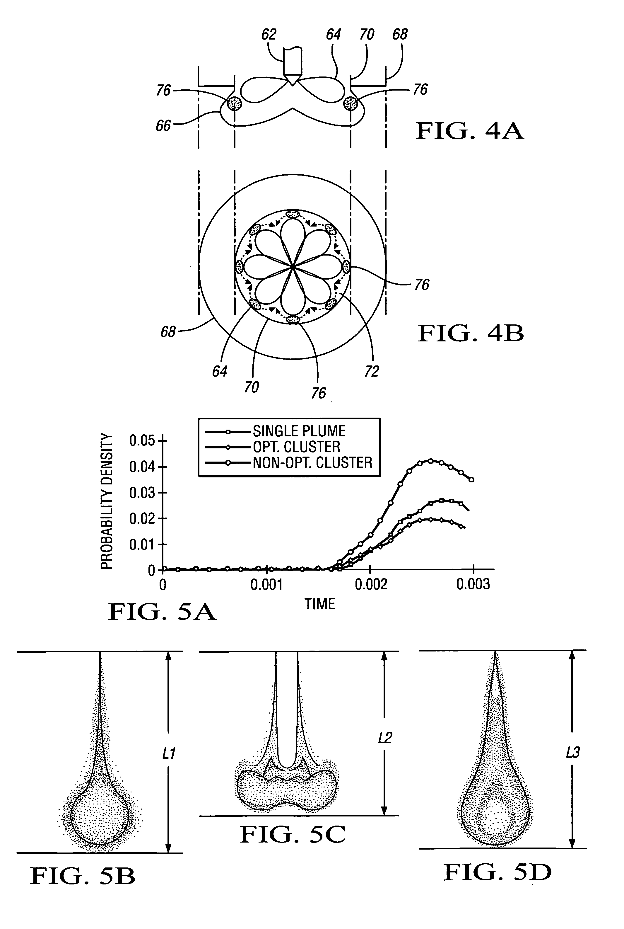
[0005] The present invention aims at addressing the need for creating a fuel injection system enabling smaller holes while maintaining sufficient, while not excessive, spray penetration. In the present invention, each hole of a conventional multi-hole nozzle is replaced by two smaller, closely spaced holes in a cluster configuration. The holes within a cluster are configured one above the other, in two horizontal planes or rows, spaced a distance apart from one another. The distance “d” between the nozzle holes in the cluster configuration, the clustered plume angle “α”, which is the angular separation between the centerlines of the nozzle holes, as well as the included spray angle “β”, are subject to optimization. “α” and “d” influence mainly the soot formation, whereas “β” the included spray angle, is chosen such that the soot oxidation is maximized. The results of a computational fluid dynamics analysis indicate that angle α set at 20 degrees results in an optimized cluster distribution. By utilizing clusters of holes, the layout of which is subject to careful optimization through computational fluid dynamics and combustion modeling, an optimal compromise can be found between liquid penetration, spray penetration and air entrainment, while minimizing soot emissions.
[0006] Specifically, the invention provides a fuel injector assembly for an engine including a fuel injector defining an outlet cluster having a first opening defined within a first plane and a second opening defined within a second plane. The second plane is parallel to and spaced from said first plane. The fuel injector is operable to emit a first plume through the first opening, and a second plume through the second opening, with the first and second plumes intermixing to form a cluster plume effective for reducing soot emissions. Preferably, the first and second planes are substantially horizontal. The second plane is preferably spaced from the first plane by a distance, with the distance being such that the cluster plume has a hydraulic flow rate substantially equivalent to that of a single plume having been delivered from a single opening, while resulting in lower overall soot formation. The first plume may exit the first opening in a first direction, with the second plume exiting the second opening in a second direction, with the first and second directions defining an angular separation therebetween. The angular separation is preferably twenty degrees.
[0007] The fuel injector may further define a second outlet cluster having a third opening defined within a third plane and a fourth opening defined within a fourth plane. The fourth plane is preferably parallel to and spaced from the third plane. The fuel injector is preferably operable to emit a third plume through the third opening and a fourth plume through the fourth opening, with the third and fourth plumes preferably intermixing to form a second cluster plume effective for reducing soot emissions. In one aspect of the invention, the first and third planes are coextensive, while the second and fourth planes are coextensive, such that the openings are arranged in two rows about the fuel injector. In another aspect of the invention, the outlet cluster and the second outlet cluster have substantially equivalent spray angles, such that the outlet cluster and the second outlet cluster are substantially symmetrically arranged about the fuel injector.

Problems solved by technology

This constitutes a particular challenge in situations where excessive external exhaust gas recirculation (EGR) is applied to control emissions of nitrogen oxides (NOx).
However, this generally has a negative influence on soot emission due to limited oxygen availability during the combustion process.

Method used


Image

  • Injector double row cluster configuration for reduced soot emissions
  • Injector double row cluster configuration for reduced soot emissions
  • Injector double row cluster configuration for reduced soot emissions

Examples


Embodiment Construction

[0019] Referring to the drawings, wherein like numerals represent like parts, FIG. 1 illustrates a schematic cross-sectional view through an injector system 10 having an injector needle 12 and an injector body 14. As used herein, terms such as “vertical” and “horizontal” describe the injector system 10 with respect to FIG. 1 of the drawings. It should be appreciated that the system 10 could be oriented differently without compromising the inventive concept. A first outlet cluster includes first and second openings 16, 18. As shown in FIG. 1, the first opening 16 generally lies in a first horizontal plane 17, while the second opening 18 generally lies in a second horizontal plane 19, with the two planes 17, 19 spaced a distance apart from one another. Thus the openings 16, 18 constituting the first outlet cluster are shown in a “vertical cluster configuration” when viewed in FIG. 2. Put another way, the injector needle 12 preferably defines a centerline C, with the first opening 16, ...


PUM


Abstract

A direct injection fuel injector system includes a fuel injector defining nozzle holes in an optimized cluster configuration. Each hole of a conventional multi-hole nozzle is replaced by two smaller, closely spaced holes in a two-hole-per-cluster configuration. The holes within a cluster are configured one above the other, in two horizontal planes or rows, spaced a distance apart from one another. The distance “d” between the nozzle holes in the cluster configuration, the clustered plume angle “α”, which is the angular separation between the centerlines of the nozzle holes, as well as the included spray angle “β”, are optimized through computational fluid dynamics and combustion modeling so that an optimal compromise can be found between liquid penetration, spray penetration and air entrainment, whereby to minimize soot emissions.

Description

CROSS REFERENCE TO RELATED APPLICATION [0001] This application claims the benefit of U.S. Provisional Patent Application Ser. No. 60 / 669,129, filed Apr. 6, 2005, and which is hereby incorporated by reference in its entirety.TECHNICAL FIELD [0002] The present invention relates to a direct injection fuel injector system with nozzle holes in an optimized cluster configuration. BACKGROUND OF THE INVENTION [0003] Direct injection engines have an open combustion chamber into which fuel is injected directly. In a direct injection engine, such as a diesel or spark ignition direct engine operating with multi-hole nozzles, the injected fuel meets a high-temperature and high-pressure environment. In order to ensure a clean and efficient combustion process, the injected fuel needs to mix rapidly with the surrounding air. This constitutes a particular challenge in situations where excessive external exhaust gas recirculation (EGR) is applied to control emissions of nitrogen oxides (NOx). [0004] ...

Claims


Application Information

Patent Timeline
IPC IPC(8): F02M47/02F02M63/00F02M51/00
CPCF02B1/12F02B23/0669F02B23/0672Y02T10/123F02B2275/14F02M61/182Y02T10/125F02B2023/103Y02T10/12
Inventor VOGEL, STEFANEL TAHRY, SHERIF H.HERGART, CARL-ANDERS
Owner GM GLOBAL TECH OPERATIONS LLC
Learn More