

Rotational flow silo equipped with air entrainment ridge
A technology for aeration sills and shafts, which is applied in water conservancy projects, marine engineering, embankments, etc., can solve problems such as damage, cavitation on the wall of shafts, and affect the safe operation of shafts, and achieve the effect of ensuring safe operation.
Inactive Publication Date: 2008-10-29
SICHUAN UNIV
View PDF0 Cites 32 Cited by
- Summary
- Abstract
- Description
- Claims
- Application Information
AI Technical Summary
Problems solved by technology
However, when the water head is high, the flow rate is high (about 1200m3 / s) and the vertical shaft swirling flow is used for energy dissipation, it is found that the flow velocity in the middle and lower part of the shaft of the spillway shaft is very high (about 40m / s), and the cavitation number of the water flow is small ( about 0.15), therefore, the shaft wall is prone to cavitation and cavitation erosion, which will be damaged by cavitation and affect the safe operation of the vertical shaft swirling flood discharge
Method used
View moreImage
Smart ImageViewing Examples

Examples
Embodiment
Login to View More PUM
 Abstract
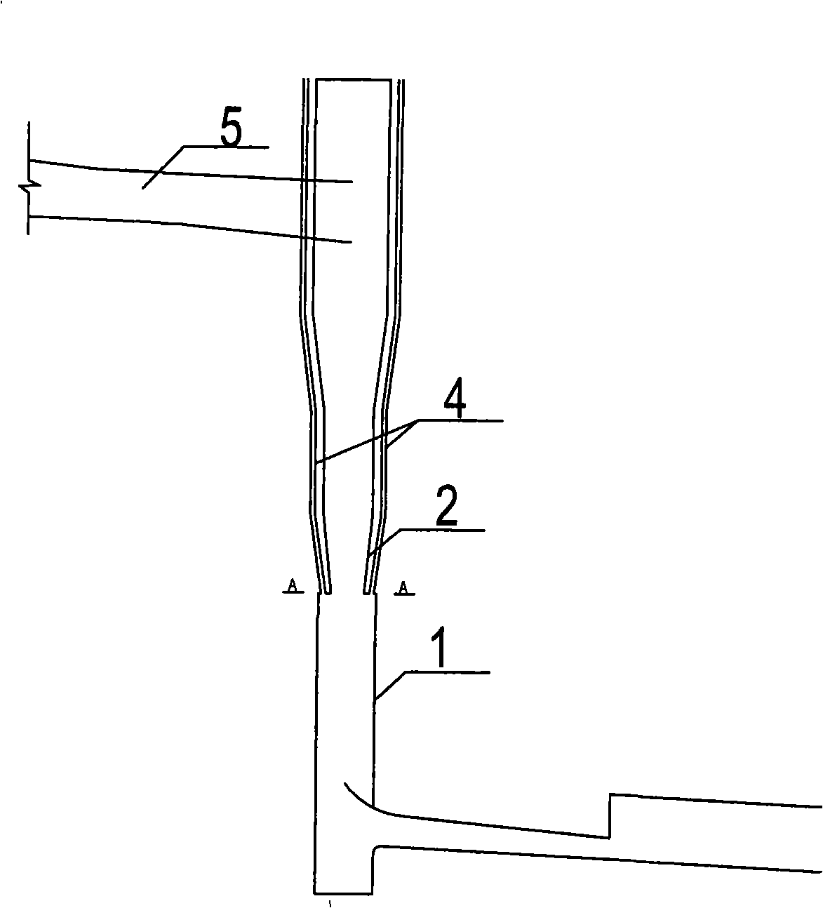
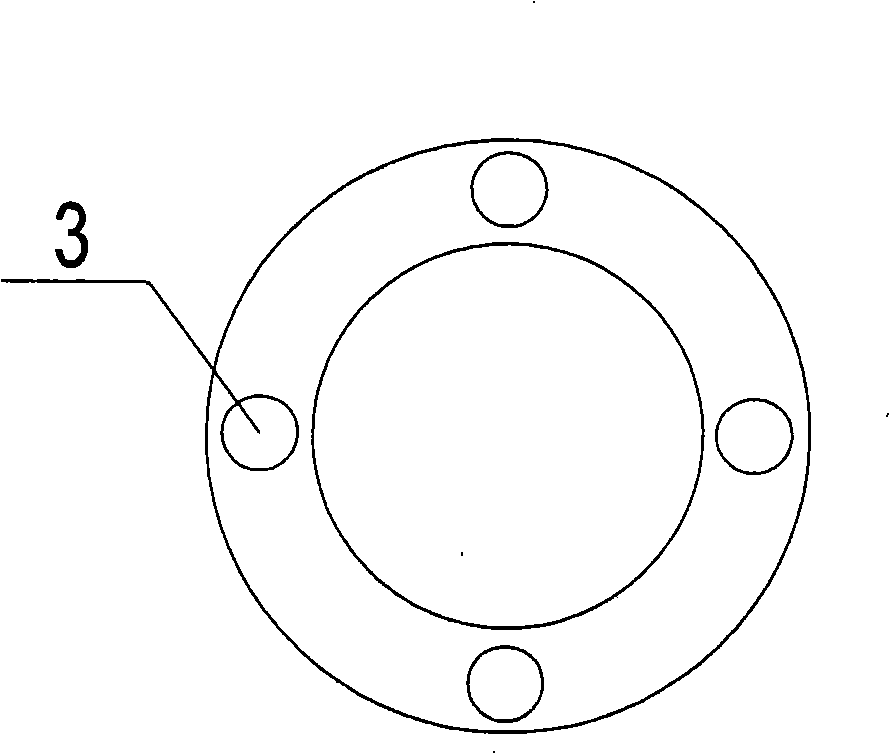
The invention discloses a gyrating drilled shaft provided with an aeration ridge. The invention is characterized in that the gyrating drilled shaft is provided with an aeration ridge on the wall surface at the middle lower part of the drilled shaft section, the aeration ridge is formed by gradually shrinking the drilled shaft connected with the upper flat section of a flood discharging tunnel from the middle part to the middle lower part and then suddenly expanding the wall surface, and at least two aeration holes are distributed on the annular aeration ridge formed by the sudden expansion, each of the aeration holes is spliced with a vent pipe communicating with the atmosphere. The vent pipes can be selectively buried on the outer side of the gyrating drilled shaft. The gyrating drilled shaft disclosed by the invention enables near-wall water layers at the lower reaches of the aeration ridge to become into aerated water flows, thereby increasing the flow cavitation number, playing the effects of air entrainment and cavitation prevention, preventing the overflowing section at the middle lower part of the drilled shaft from being damaged by cavitation erosion, and ensuring the safe flood discharging operation of the gyrating drilled shaft.
Description
A swirl shaft provided with an aeration sill technical field The invention belongs to the technical field of aeration and corrosion reduction in a swirl shaft in a water conservancy project, and in particular relates to a swirl shaft provided with an aeration sill. Background technique So far, the research on the swirl shaft spillway tunnel has been relatively in-depth, whether it is from the perspective of combining numerical simulation and model tests to analyze the hydraulic characteristics of the swirl shaft spillway tunnel and to continuously analyze the shape of the swirl shaft spillway tunnel. The optimization of the swirl shaft flood discharge tunnel has a relatively deep understanding of the basic flow state, discharge capacity, diameter of the circulation cavity, wall pressure distribution characteristics, ventilation volume of the vent hole, and energy dissipation rate, etc., and the swirl shaft Flow shaft flood discharge tunnel is also more and more favored by ...
Claims
Login to View More Application Information
Patent Timeline
 Patent Type & AuthorityApplications(China)
IPC IPC(8): E02B8/06E02B3/10
Inventor邓军刘善均许唯临王韦张建民曲景学
OwnerSICHUAN UNIV