Method and system for controlling engine

a technology of engine control and control system, applied in the direction of engine control, electric control, combustion engines, etc., can solve the problems of low engine torque generation, and low efficiency of post-injection fuel, so as to reduce the generation of soot, improve fuel efficiency, and reduce the effect of soot emission

Active Publication Date: 2020-02-25
MAZDA MOTOR CORP
View PDF68 Cites 5 Cited by
  • Summary
  • Abstract
  • Description
  • Claims
  • Application Information

AI Technical Summary

Benefits of technology

The present disclosure is made in view of the above situations and aims to achieve both reduction of soot emission and improvement of fuel efficiency.
Also according to this method, the fuel of the main injection and the fuel of the second injection do not mix with each other and reduce the generation of soot, and the fuel of the second injection for stimulating the oxidation of the soot also contributes in generating the engine torque. Therefore, both the reduction of soot emission and improvement of fuel efficiency are achieved.

Problems solved by technology

Therefore, the fuel of the post injection does not contribute much to generating an engine torque.
Although the post injection is effective for reducing soot emission, it is disadvantageous for fuel efficiency.
However, this causes an interval between the main injection and the post injection to be shorter; therefore, a fuel concentration becomes locally high and a new issue of soot generation arises.

Method used


Image

  • Method and system for controlling engine
  • Method and system for controlling engine
  • Method and system for controlling engine

Examples


Embodiment Construction

Hereinafter, one embodiment of a control system of an engine is described in detail with reference to the accompanying drawings. The following description gives one example of the control system of the engine.

(Configuration of Diesel Engine System)

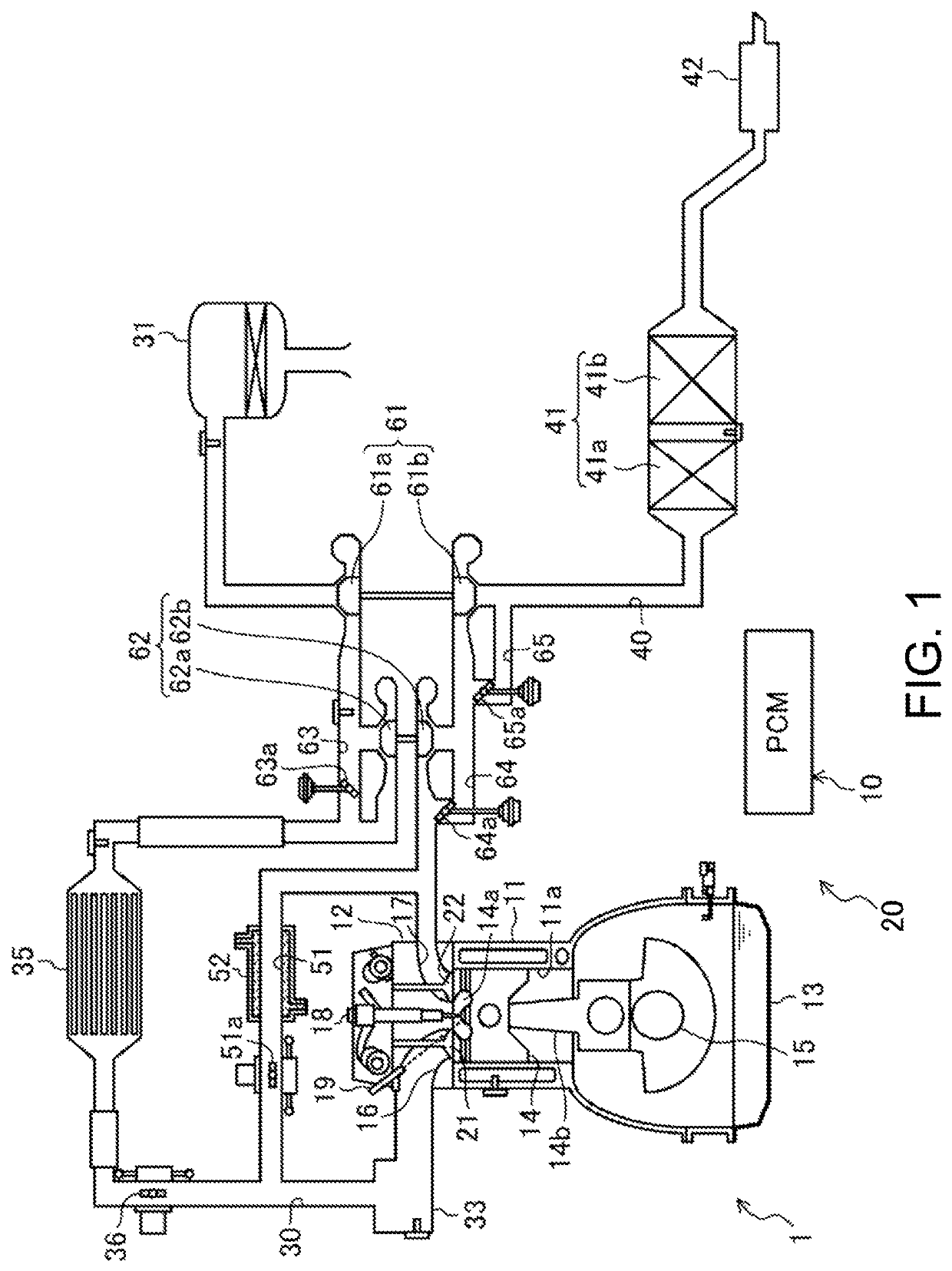
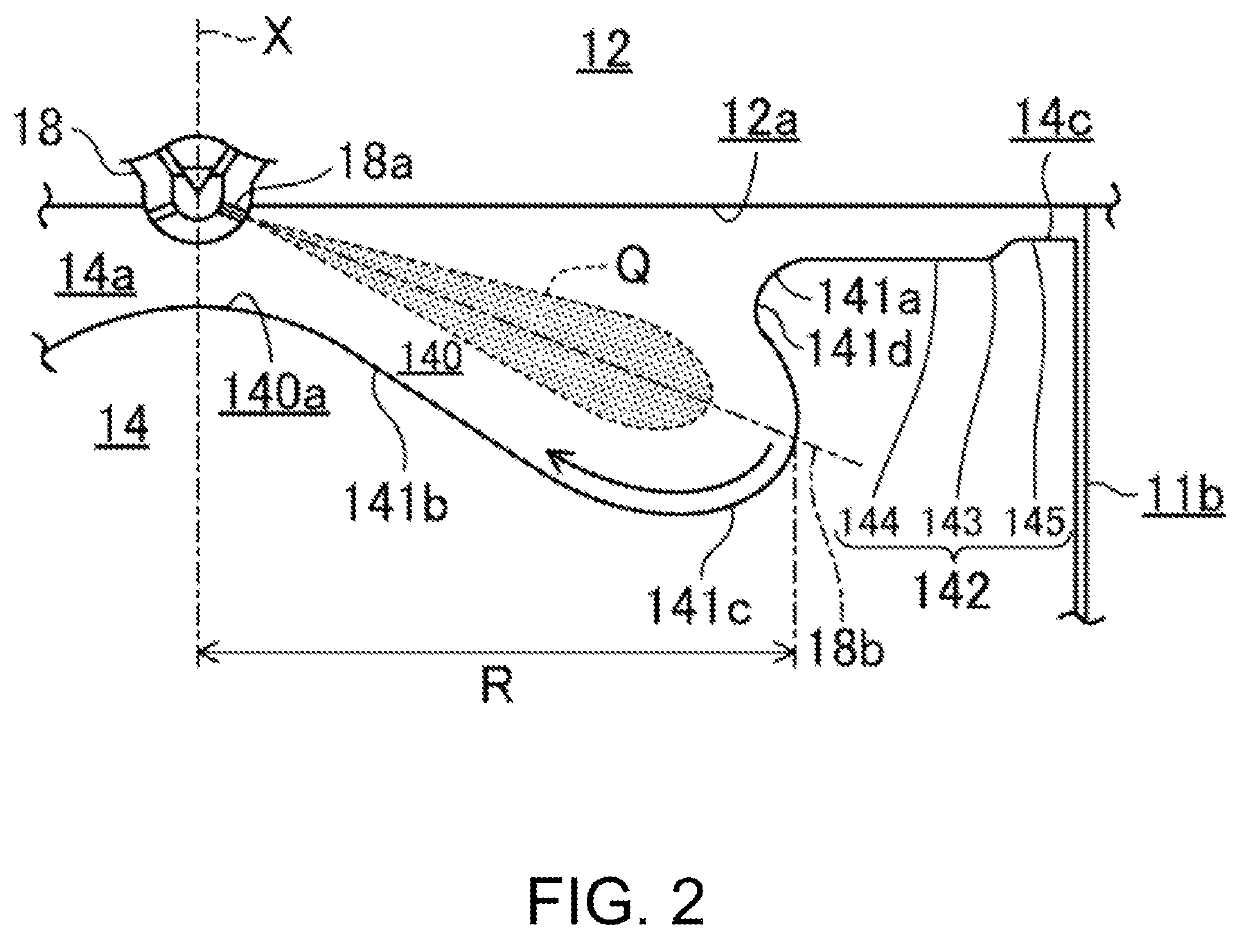
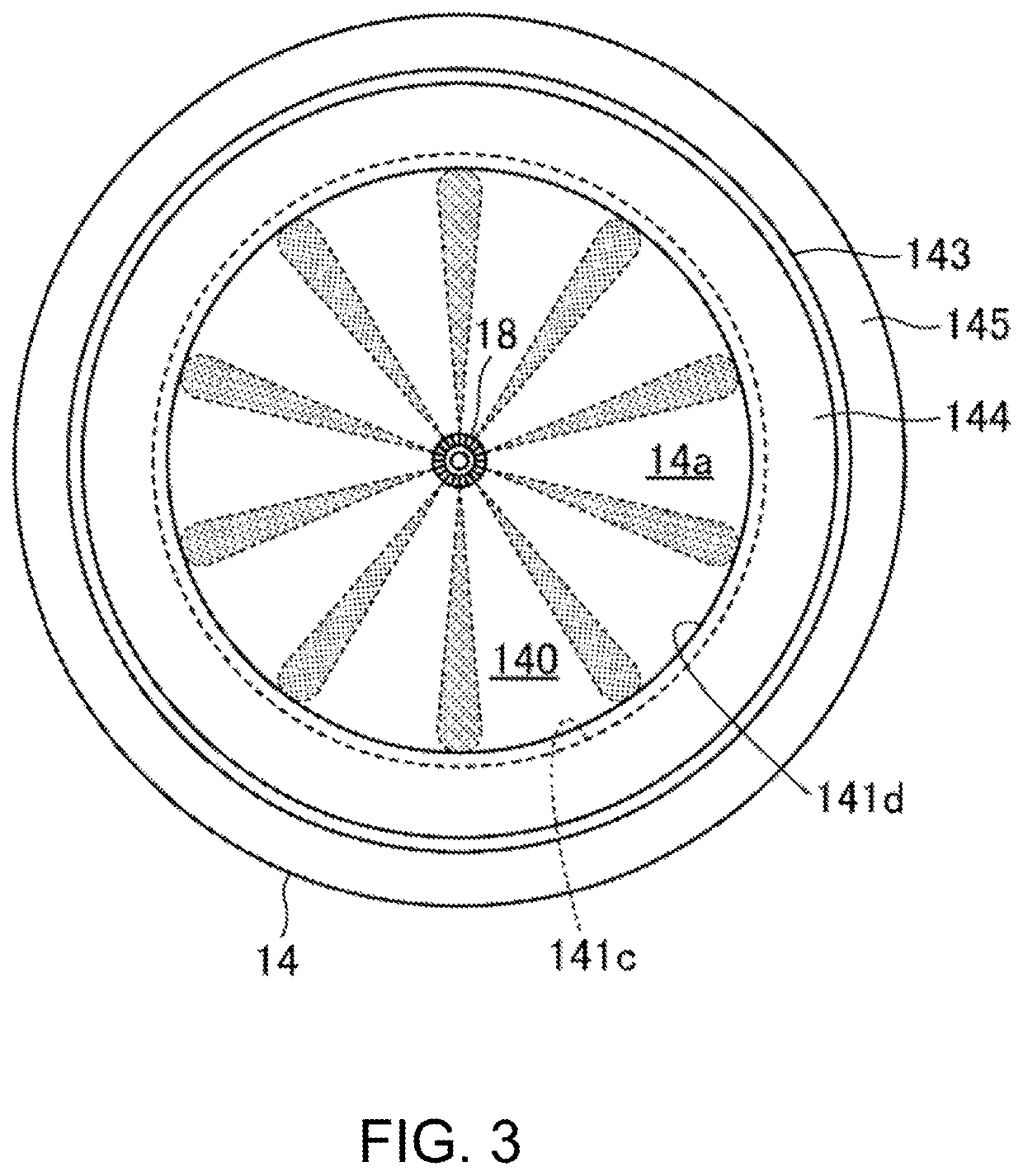
FIG. 1 illustrates a schematic configuration of the engine 1. FIGS. 2 and 3 illustrate a configuration of a combustion chamber 14a of the engine 1. The engine 1 is a diesel engine mounted on, for example, a four-wheel automobile and is supplied with fuel containing diesel fuel as a main component. The automobile travels by the engine 1 operating. The engine 1 includes a cylinder block 11 formed with a plurality of cylinders 11a (only one is illustrated in FIG. 1), a cylinder head 12 disposed on the cylinder block 11, and an oil pan 13 disposed below the cylinder block 11 that stores lubricating oil. A piston 14 is fitted into each cylinder 11a of the engine 1 to reciprocate along a cylinder center axis X. The piston 14 is coupled to a cran...


PUM


Abstract

A control system of an engine is provided, which includes a piston formed with a cavity and configured to reciprocate in a cylinder along a center axis of the cylinder, and a fuel injector disposed facing a top surface of the piston and configured to inject fuel along an injection axis. When the piston is located near a top dead center of compression stroke, the fuel injector performs a first injection so that the fuel flows from the fuel injector toward the cavity along the injection axis, collides with an inner surface of the cavity, then flows back toward the fuel injector along the inner surface of the cavity from a position offset from the injection axis. The fuel injector performs a second injection toward the cavity at a timing after the first injection and at which the fuel of the first injection flows back.

Description

TECHNICAL FIELDThe present disclosure relates to a method and system for controlling an engine.BACKGROUND OF THE DISCLOSUREJP2012-031844A discloses a diesel engine which performs a main injection and a post injection. The post injection stimulates oxidation of soot generated in a combustion chamber and reduces emission of soot.The diesel engine described in JP2012-031844A performs the post injection at such a timing that a portion of the fuel injected by a fuel injector reaches outside of a cavity formed in a piston. That is, the post injection is performed on expansion stroke when the piston descends from a top dead center of compression stroke. Therefore, the fuel of the post injection does not contribute much to generating an engine torque. Although the post injection is effective for reducing soot emission, it is disadvantageous for fuel efficiency.In this regard, advancing the timing of the post injection is advantageous for increasing the engine torque and improving thermal ef...

Claims


Application Information

Patent Timeline
Patent Type & Authority Patents(United States)
IPC IPC(8): F02B23/06F02F3/28F02D41/40F02D41/38
CPCF02B23/0672F02D41/402F02F3/28F02B23/0645F02B23/0651F02B23/0669F02D41/401F02D2250/38F02D2200/101F02D2200/0406F02D2041/389Y02T10/12Y02T10/40
Inventor FUKUDA, DAISUKETAGUCHI, AKIRAMINAMOTO, HIROSHISHIRAHASHI, NAOTOSHIKATO, YUDAIKAKUDA, YOSHIESAGANE, YASUYUKIKIM, SANGKYUSHIMO, DAISUKEHIRABAYASHI, KAZUNORI
Owner MAZDA MOTOR CORP
Why Eureka
Try Eureka