Fuel injection pattern and timing

a fuel injection and timing technology, applied in the direction of electrical control, process and machine control, instruments, etc., can solve the problems of unsatisfactory nitrogen and oxygen compounds, nox pollutants, etc., and achieve the effect of limiting soot emissions and minimizing soot emissions

Active Publication Date: 2013-06-27
INT ENGINE INTPROP CO LLC
View PDF12 Cites 2 Cited by
  • Summary
  • Abstract
  • Description
  • Claims
  • Application Information

AI Technical Summary

Benefits of technology

[0008]Aspects and embodiments of the present technology described herein relate to one or more systems and methods for controlling the operation of an engine. According to at least one aspect of the present technology, at least one method is provided for operating an engine to limit soot emissions during fuel enriched engine operation. The method includes operating the engine using a first fuel injection pattern and timing to inject fuel into a combustion chamber of the engine. The method further includes receiving a request for an increased engine power output and operating the engine using a second fuel injection pattern and timing to inject more fuel into the combustion in response to the request for the increased power output. In at least one embodiment, the second fuel injection pattern and timing is configured to minimize soot emissions during enriched fuel operations, such as during transient operations.

Problems solved by technology

Such mixtures are referred to as a “lean mixture.” Combustion of lean air and fuel mixtures by an internal combustion engine, however, creates high combustion temperatures that result in formation of undesirable nitrogen and oxygen compounds, i.e., NOx pollutants.

Method used


Image

  • Fuel injection pattern and timing
  • Fuel injection pattern and timing
  • Fuel injection pattern and timing

Examples


Embodiment Construction

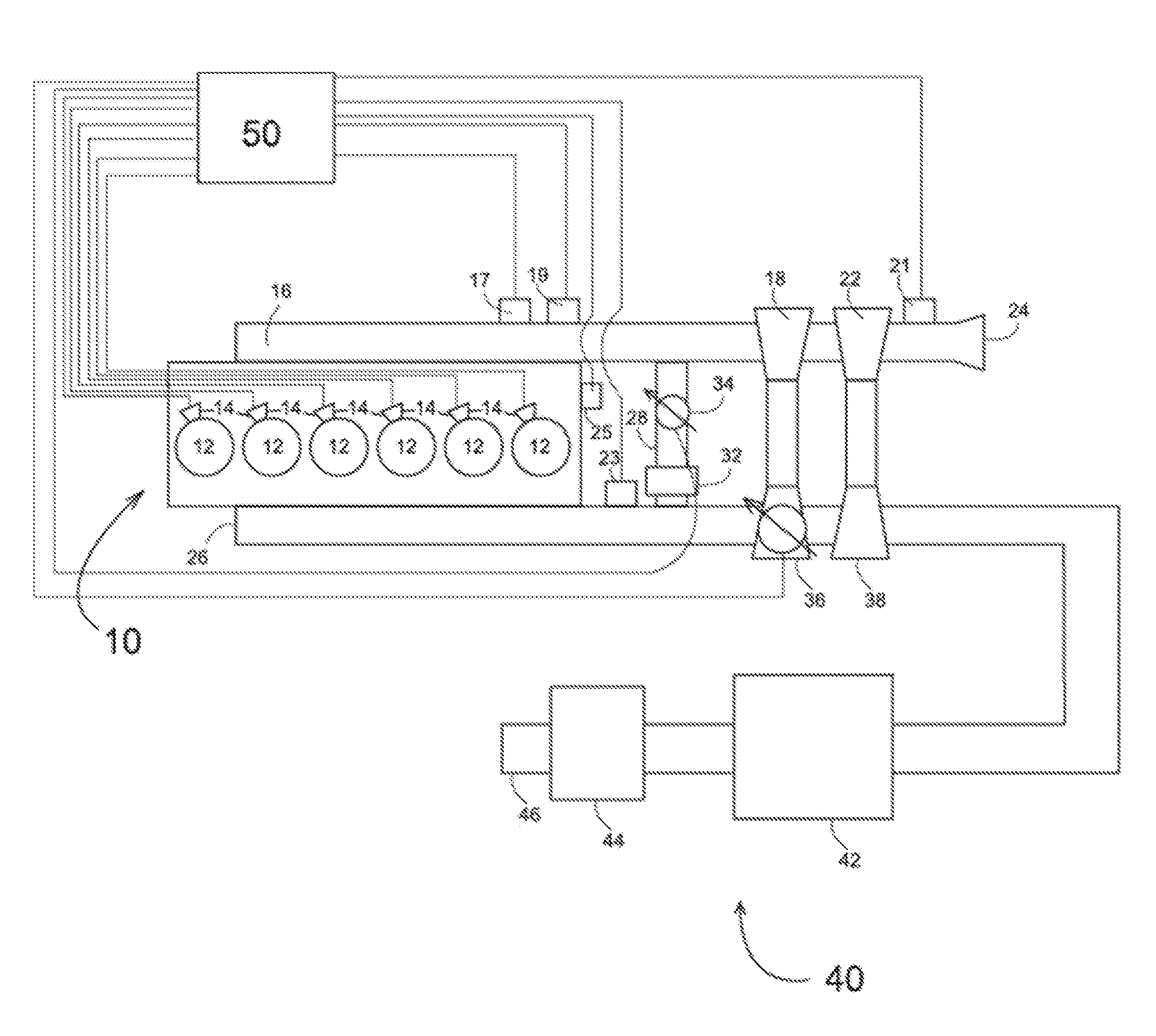
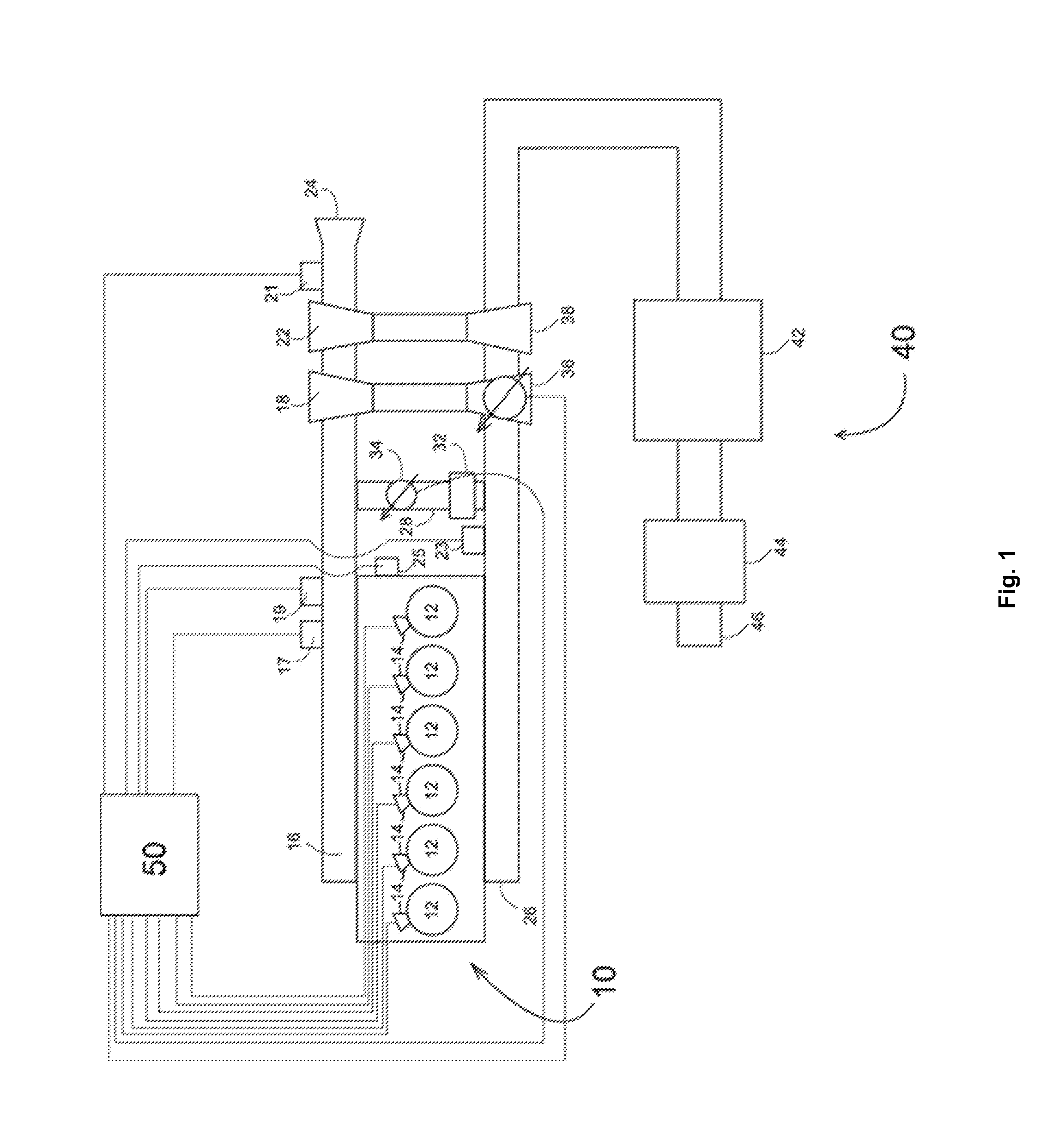
[0021]Aspects and embodiments of the present technology described herein concern control of an internal combustion engine. In particular, some aspects and embodiments concern control of an internal combustion engine to limit emission of undesirable combustion products. Other aspects and embodiments concern improving transient response of an internal combustion engine to requests for increased power while limiting or reducing emission of undesirable combustion products (e.g., soot).

[0022]Various examples of embodiments of the present technology will be described more fully hereinafter with reference to the accompanying drawings, in which such examples of embodiments are shown. Like reference numbers refer to like elements throughout. Other embodiments of the presently described technology may, however, be in many different forms and are not limited solely to the embodiments set forth herein. Rather, these embodiments are examples representative of the present technology. Rights based...


PUM


Abstract

A method is provided for operating an engine to limit soot emissions during fuel-enriched operation. The method includes operating the engine using a first fuel injection pattern and timing to inject fuel into a combustion chamber of the engine. The method further includes receiving a request for an increased engine power output and operating the engine using a second fuel injection pattern and timing to inject more fuel into the combustion in response to the request for the increased power output, where the second fuel injection pattern and timing is configured to minimize soot emissions during enriched fuel operations, such as during transient operations.

Description

RELATED APPLICATIONS[0001][Not Applicable]FEDERALLY SPONSORED RESEARCH OR DEVELOPMENT[0002][Not Applicable]MICROFICHE / COPYRIGHT REFERENCE[0003][Not Applicable]FIELD[0004]This disclosure relates to the operation of an internal combustion engine. Aspects and embodiments of the presently described technology relate to operation during transient power operation of the engine.BACKGROUND[0005]Increasing fuel efficiency of internal combustion engines and limiting their emission of undesirable combustion products are studied objects of engine control. Fuel efficiency is increased by limiting the amount of fuel provided to the engine during engine operation at constant or slowly changing engine speed under low engine loads. Providing a limited amount of fuel to the engine creates a mixture of air and fuel that contains more air than is required for combustion of the fuel. Such mixtures are referred to as a “lean mixture.” Combustion of lean air and fuel mixtures by an internal combustion eng...

Claims


Application Information

Patent Timeline
Patent Type & Authority Applications(United States)
IPC IPC(8): F02D41/30
CPCF02D41/30F02D41/10F02D41/401Y02T10/44F02D35/028F02D2250/38F02D41/403Y02T10/40
Inventor CATTANI, LUIS CARLOSUCHANSKI, MICHAELRODIGUEZ, ROGELIOCHEN, JER SHEN JASONKHADILKAR, DILEEPRAJAMPETA, RAHUL DEVSCHIPPER, JEREMY GRANTKASTANIS, ERIC
Owner INT ENGINE INTPROP CO LLC
Why Eureka
Try Eureka