Apparatus and method for extinguishing fires in a multi-floored building

a multi-floored building and apparatus technology, applied in fire rescue and other directions, can solve the problems of difficult fire extinguishing, windows blowing out, more difficult situations, etc., and achieve the effect of restricting the backtracking of the rollers

Inactive Publication Date: 2011-04-12
HERO SYST
View PDF22 Cites 3 Cited by
  • Summary
  • Abstract
  • Description
  • Claims
  • Application Information

AI Technical Summary

Benefits of technology

The bracing system of this aspect of the invention may further comprise a retaining bar attached to the tubular structure and engageable with a portion of the bracing system to further restrict backtracking of the boom towards the entry end of the guide.
The bracing system of this aspect of the invention may further comprise a bracket attached to the frame and aligned with a portion of the retaining bar. The bracket has a receiver into which the portion of the retaining bar is received to prevent backtracking of the boom.
The bracing system of this aspect of the invention may further comprise a retainer bar attached to the tubular structure and engageable with a portion of the frame to further restrict backtracking of the rollers.

Problems solved by technology

It is often difficult to extinguish a fire in a high-rise building because the floor or floors on which the fire is located is / are inaccessible due to the heat accompanying the fire.
This excessive heat will often cause windows to blow out.
The open windows allow oxygen to feed the fire creating an even more difficult situation.
Many times, these sprinkler systems are not sufficient to battle a hot and out of control fire, especially when the windows of the building have already blown out.
However, when the floor is beyond the reach of the waterway, there is very little chance that firefighters will be able to access the burning floors until some cooling takes place.
One drawback of the method and apparatus of the '883 patent is the difficulty in hoisting the tubular member outwardly from the lower floor access and upwardly to the second floor access.

Method used


Image

  • Apparatus and method for extinguishing fires in a multi-floored building
  • Apparatus and method for extinguishing fires in a multi-floored building
  • Apparatus and method for extinguishing fires in a multi-floored building

Examples


Embodiment Construction

While this invention is susceptible of embodiments in many different forms, there is shown in the drawings and will herein be described in detail preferred embodiments of the invention with the understanding that the present disclosure is to be considered as an exemplification of the principles of the invention and is not intended to limit the broad aspect of the invention to the embodiments illustrated.

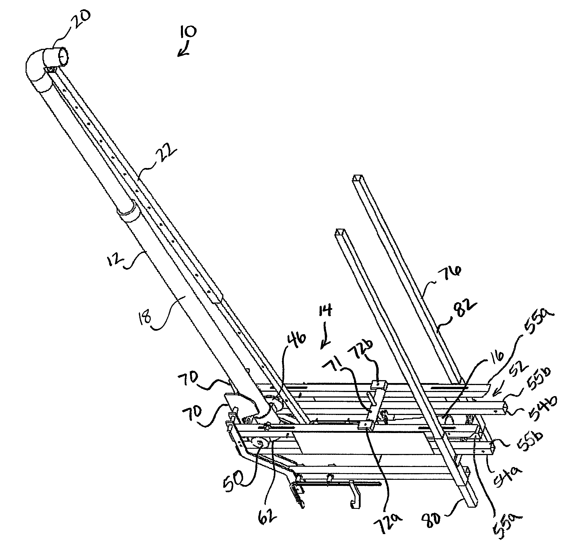
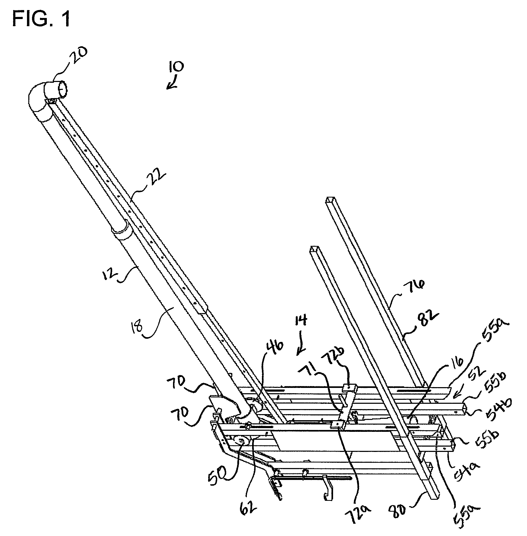
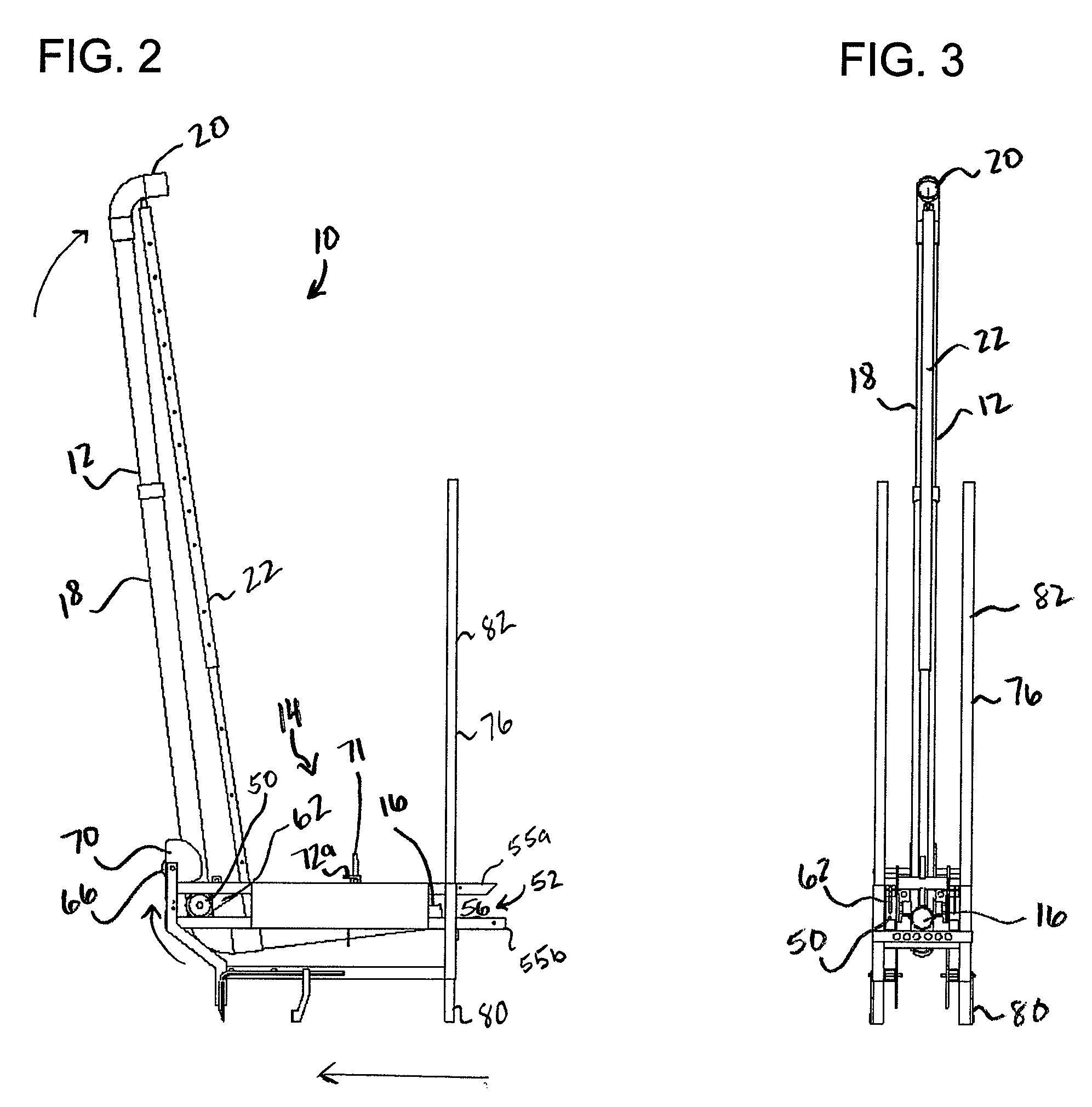
LISTING OF REFERENCE NUMBERS

Apparatus 10;

Curvilinear tubular structure 12;

Bracing system 14;

Inlet 16;

Intermediate portion 18;

Outlet 20;

Telescoping support member 22;

Rigid frame 44;

Boom 46;

Boom roller 50;

Guide 52

Tracks 54a,b;

Rails 55a,b;

Entry end of guide 56;

Terminal end of guide 58

Keepers 62;

Stabilizer roller 66;

Plates 70;

Retainer bar 71;

Brackets 72a,b;

Extendable frame 76

Extendable frame lower portion 80; and

Hydraulic jacks 82.

The present invention is directed to an apparatus for treating a fire in a multi-floored building, a method of treating fire in a multi-floored building, an...


PUM


Abstract

An improved apparatus for treating a fire in a multi-floored building where the fire is located on an upper floor vertically displaced from a lower floor from which the fire is treated, and where the upper and lower floors each have a selectively openable environmental access along an external wall of the multi-floored building. The improved apparatus includes a tubular structure having an inlet, an intermediate portion, and an outlet and a bracing system. The bracing system has a frame, a first pivot point, and a second pivot point. The frame provides support against a sturdy surface. The tubular structure is supported on the first pivot point and rotates thereon to elevate or hoist the outlet towards the upper floor environmental access. The tubular structure is further supported on a second pivot point and further rotates thereon to elevate the outlet.

Description

TECHNICAL FIELDThe invention relates to an apparatus for fighting fires. More specifically, the present invention relates to an apparatus including a portable apparatus and method for extinguishing a fire in a multi-floored building.BACKGROUNDIt is often difficult to extinguish a fire in a high-rise building because the floor or floors on which the fire is located is / are inaccessible due to the heat accompanying the fire. This excessive heat will often cause windows to blow out. The open windows allow oxygen to feed the fire creating an even more difficult situation.High-rise buildings typically have sprinkler systems to help extinguish fires and help firefighters access the burning floors. Many times, these sprinkler systems are not sufficient to battle a hot and out of control fire, especially when the windows of the building have already blown out. Some older buildings have no sprinkler systems at all. If the fire is located on a lower floor, a fire truck waterway can be used to ...

Claims


Application Information

Patent Timeline
Patent Type & Authority Patents(United States)
IPC IPC(8): A62C3/00A62C99/00
CPCA62C3/02A62C31/28A62C31/005A62C35/58
Inventor WIELGAT, MICHAELKEGG, DANIEL J.
Owner HERO SYST
Why Eureka
Try Eureka