Mouse pad apparatus

Inactive Publication Date: 2011-04-12
RAMSARRAN VIJAY +1
View PDF17 Cites 9 Cited by
  • Summary
  • Abstract
  • Description
  • Claims
  • Application Information

AI Technical Summary

Benefits of technology

[0010]Another object of the mouse pad apparatus is to rem

Problems solved by technology

This does not, though, provide the best solution, as total redesign of a lap

Method used


Image

  • Mouse pad apparatus
  • Mouse pad apparatus
  • Mouse pad apparatus

Examples


Example

DETAILED DESCRIPTION OF THE DRAWINGS

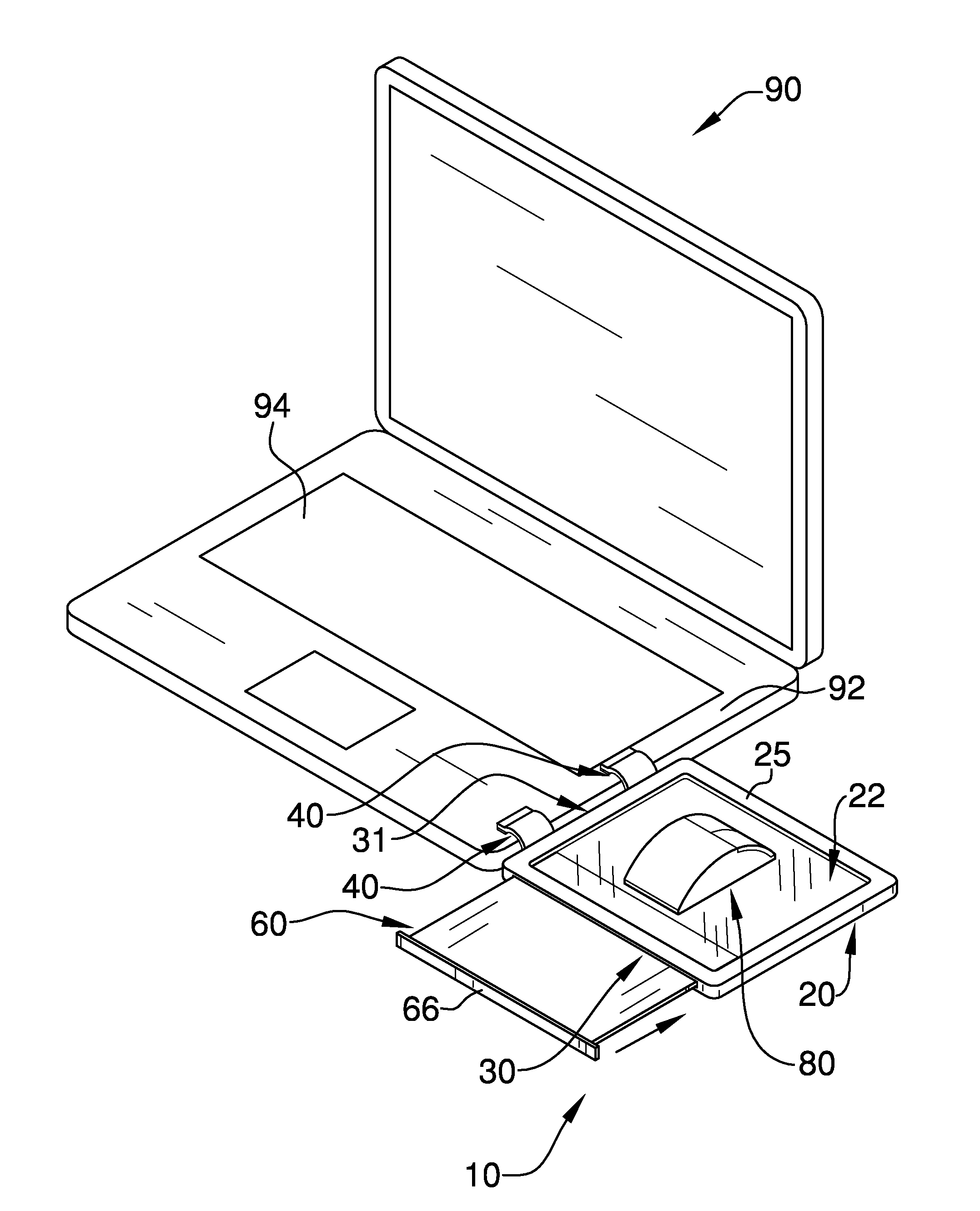
[0020]With reference now to the drawings, and in particular FIGS. 1 through 4 thereof, the principles and concepts of the mouse pad apparatus generally designated by the reference number 10 will be described.

[0021]Referring to FIG. 1, the mouse pad apparatus 10 removably attaches to the edge 92 of an existing laptop computer 90. The apparatus 10 attaches to the computer 90 via the spaced apart flex clips 40 affixed to the first side 31 of the platform 20. The apparatus 10 platform surface 22 provides an operational surface 22 for an existing mouse 80. The border 25 of the platform 20 provides a boundary elevated above the surface 22 so that the mouse 80 is slideably captured. The pull out tray 60 with grip tab 66 provides for additional needs such as an added work surface, for example.

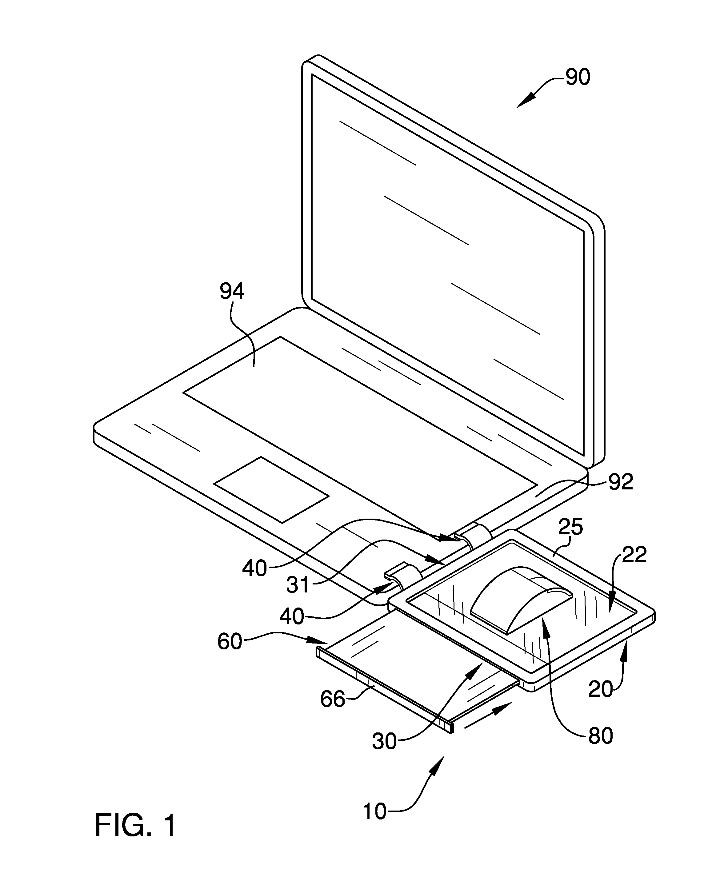
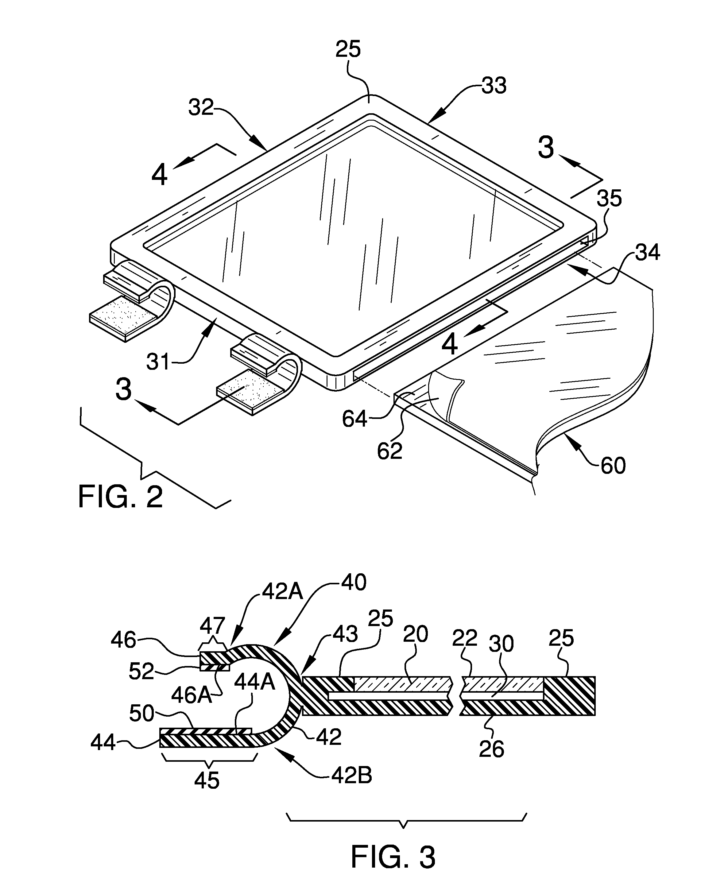
[0022]Referring to FIGS. 2-4, the apparatus 10 further comprises the rectangular platform 20 with border 25 having a first side 31 spaced apart from a third side 33,...


PUM


Abstract

The mouse pad apparatus removably attaches to a laptop computer via spaced apart flex clips affixed to one side of the platform border. The mouse pad platform is optionally transparent and textured and provides for use of a mouse with a laptop computer. The flex clips provide a positive, cushioned, frictional engagement of the apparatus with the edge of the computer. The slot within the platform provides for the pull out tray which can retain a writing surface, photo, or other material, visible through the transparent platform surface.

Description

CROSS-REFERENCE TO RELATED APPLICATIONS[0001]Not ApplicableFEDERALLY SPONSORED RESEARCH OR DEVELOPMENT[0002]Not ApplicableINCORPORATION BY REFERENCE OF MATERIAL SUBMITTED ON A COMPACT DISK[0003]Not ApplicableBACKGROUND OF THE INVENTION[0004]The portability of laptop computers has seen such in greater acceptance daily. Laptop computers, though, do not typically include a mouse pad, but instead usually have a touch pad. Not all users prefer a touch pad, even if their preference either by need or desire is a laptop computer. Previously, some have proposed a pull out mouse pad built into a laptop. This does not, though, provide the best solution, as total redesign of a laptop is required, and such does not provide for retrofit to existing laptops. What has been needed is a mouse pad apparatus that universally and removably fits virtually all laptop computers. The present mouse pad apparatus provides such, along with other desirable useful features.FIELD OF THE INVENTION[0005]The mouse p...

Claims


Application Information

Patent Timeline
IPC IPC(8): A47G29/00B41J11/02
CPCG06F3/0395A47G1/0616Y10S248/918
Inventor RAMSARRAN, VIJAYARMAN, KAMILLE
Owner RAMSARRAN VIJAY
Why Eureka
Try Eureka