Method for joining metal and plastic workpieces

a technology of metal workpieces and plastic workpieces, applied in the direction of metal workpiece holders, large fixed members, supporters, etc., can solve the problems of increased device weight, high stress concentration levels, and disadvantages, and achieve the effect of convenient application

Active Publication Date: 2011-06-09
HELMHOLTZ ZENT GEESTHACHT ZENT FUER MATERIAL UND KUESTENFORSCHUNG
View PDF12 Cites 17 Cited by
  • Summary
  • Abstract
  • Description
  • Claims
  • Application Information

AI Technical Summary

Benefits of technology

[0013]Therefore, it is the object of the present invention to provide a method for joining metal and plastic workpieces and in particular for forming a lap joint which method can easily be applied and which does not have the afore-mentioned disadvantages.
[0016]Since the axial movement of the pin or the sleeve into the metal workpiece is stopped before the contact surface is reached, it is on the one hand achieved that a volume extending from the outer surface of the metal workpiece to the contact surface is plasticized in its entirety and on the other hand that the structure of the plastic workpiece is not affected or even damaged. In particular, reinforcing material inside the plastic workpiece such as fibers cannot be destroyed. However, since the entire volume is plasticized an extremely high amount of heat is transferred to the plastic workpiece so that it is melt without being substantially deformed.
[0018]In addition, after stopping rotation the material of the workpieces hardens and adhesion occurs at the interface between the workpieces. Thus, by the method of the present invention an joint is formed which is a combination of a positive joint due to the nub and an adhesive joint. However, the method does not suffer from the afore-mentioned negative effects which usually occur during production of an adhesive joint. Therefore, this method is a good candidate for substituting riveting and traditional adhesive bonding owing to its positive features.
[0020]Preferably, the penetration depth up to which either the pin or the sleeve penetrate into the metal workpiece, is below 25% of the distance between the outer surface and the contact surface of the metal workpiece and most preferably below 20%. This ensures that on the one hand the metal material is fully plasticized, i.e. the entire region between the outer surface and the contact surface, and that on the other hand the structure of the plastic surface is not damaged.
[0022]The stability of the joint can further be increased by texturing the contact surface of the metal workpiece. This leads to a more distinct positive engagement between the workpieces. A significant effect can be achieved when providing protrusions on the contact surface of the metal workpiece.
[0025]Since in the method of the present invention the structure of the plastic workpiece is prevented from being damaged, it can advantageously applied to plastic workpieces which are formed from a fiber reinforced material. Here, the fibers cannot be deformed so that the rigidity of the plastic workpiece is not affected by the joining process.

Problems solved by technology

However, these mechanical connections involve additional elements which lead to an increase of the weight of the device.
In particular, for aviation applications, this effect is disadvantageous as it is a main requirement in this field to ensure that the weight of a each device is minimized.
Further disadvantages of mechanical connections are the fact that high stress concentration levels are generated at the location of the connection, and that the connection itself may form the starting point for a crack in at least one of the components.
Finally, a connection with an additional element such as a screw or rivet may lead to an unpleasant appearance which is an often unwanted effect.
Whereas in case of connections between two metal components conventional welding techniques such as ultrasonic, resistance, vibration, infrared or induction welding, have proven to be extremely useful even in situations where only punctual connections are possible, these techniques cannot be employed in case of metal / plastic connections in the same manner as in metal / metal connections.
Further, it is disadvantageous that when traditional welding techniques are applied, often a previous surface treatment is required which is time consuming.
Moreover, welding is often connected with a high energy input, which may lead to the problem that the material in the vicinity of the welding point is significantly influenced and the material properties are altered.
Here, it has turned out that those adhesives which provide for a sufficiently stable connection, produce toxic gases at least during curing or require the application of heat so that additional measures are necessary to prevent the gases from getting into contact with workers in the vicinity of the connection formed by gluing or the materials from being altered due to the heat.
Further, it is questionable whether a joint formed by an adhesive only is sufficiently stable.
In the second example it is required that in a first step a hole is drilled into the metal workpiece which is an additional time consuming step.
Thus, this might lead to the unwanted effect that the position of the joint can easily be identified.
Finally, a hole has to be produced in the metal workpiece which leads to a reduced strength of the workpiece in the region of the joint.
Rotating the sleeve and the pin results in frictional heat and the metal workpiece will be plasticized.
In particular, reinforcing material inside the plastic workpiece such as fibers cannot be destroyed.

Method used


Image

  • Method for joining metal and plastic workpieces
  • Method for joining metal and plastic workpieces
  • Method for joining metal and plastic workpieces

Examples


Embodiment Construction

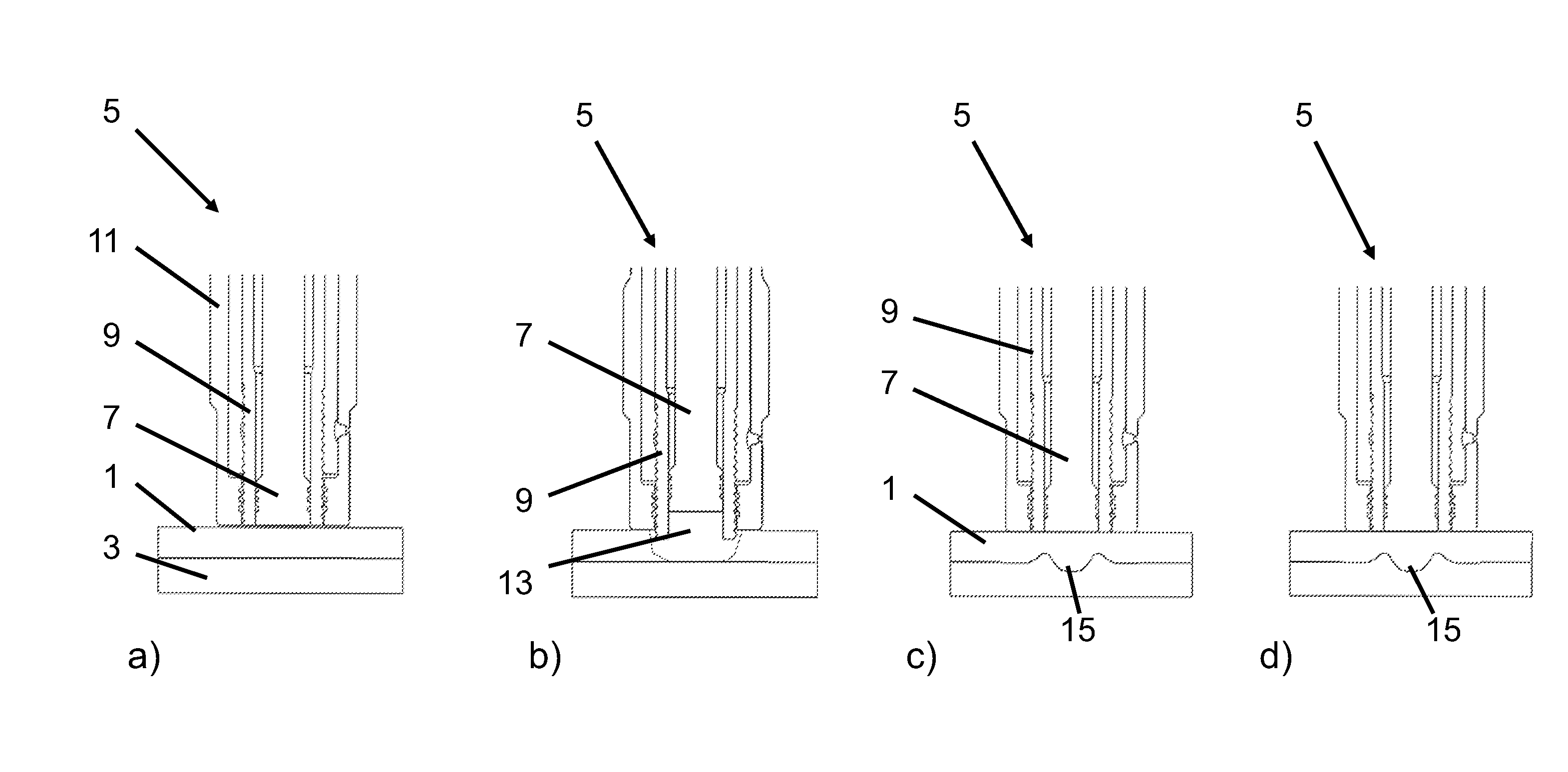
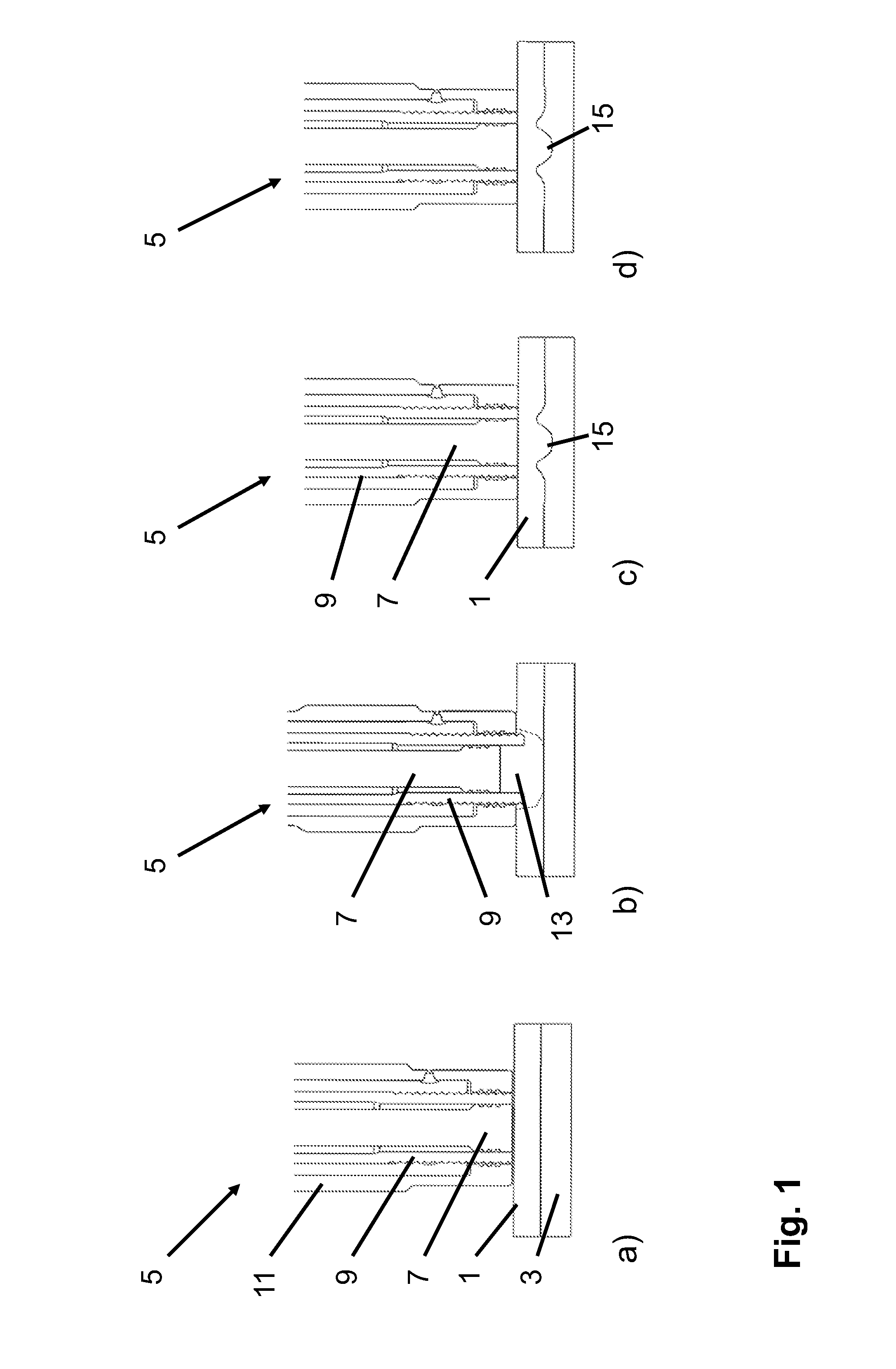
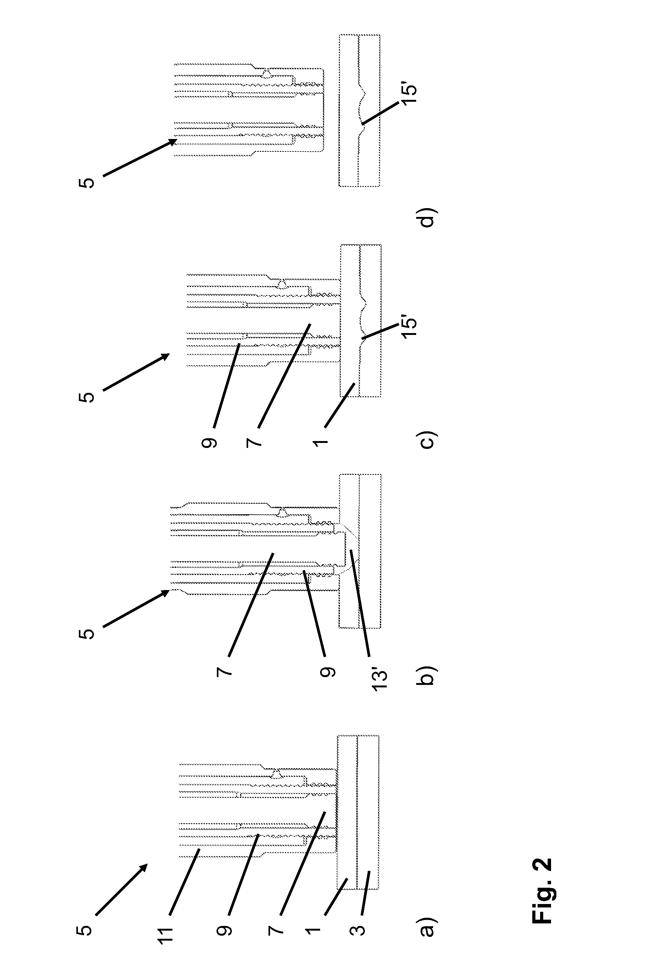
[0033]The present invention is susceptible of embodiment in many different forms. While the drawings illustrate, and the specification describes, certain preferred embodiments of the invention, it is to be understood that such disclosure is by way of example only. There is no intent to limit the principles of the present invention to the particular disclosed embodiments.

[0034]As shown in Part a) of FIG. 1 in a first step of an example of the method according to the present invention a metal workpiece 1 and a plastic workpiece 3 are positioned such that contact surfaces of the workpieces 1, 3 abut on each other and a stack is formed. Here, even though it is not shown in the schematic representation of the present example of the joining method the contact surfaces of the workpieces 1, 3 may be cleaned by grinding off these surfaces before being positioned on each other.

[0035]In the present example the metal workpiece 1 is formed of aluminum or magnesium and the plastic workpiece 3 is ...


PUM

PropertyMeasurementUnit
frictionaaaaaaaaaa
distanceaaaaaaaaaa
timeaaaaaaaaaa

Abstract

The present invention relates to a method for connecting a metal workpiece and a plastic workpiece by means of a joining tool, including positioning the metal workpiece and the plastic workpiece, bringing the front end of the pin, the sleeve and the clamping ring in contact with an outer surface of the metal workpiece, rotating the sleeve and the pin so as to generate friction between the front ends of the sleeve and the pin and the outer surface of the metal workpiece, and moving the pin and the sleeve in the axial direction while both are rotated, one of the sleeve and the pin penetrating into the metal workpiece and the other of the sleeve and the pin being retracted from the outer surface thereof. The axial movement into the metal workpiece is stopped before the one of the sleeve and the pin reaches the contact surface and after stopping the axial movement the one of the sleeve and the pin is retracted from the metal workpiece and the other is moved towards the outer surface of the metal surface until the front ends of the pin and the sleeve are on the same level.

Description

CROSS-REFERENCE TO RELATED APPLICATION[0001]The present application claims the benefit of and priority from European Patent Application Serial No. EP 09015014.5, filed Dec. 3, 2009, the entire disclosure of which is hereby incorporated by reference herein.BACKGROUND OF THE INVENTION[0002]1. Field of the Invention[0003]The present invention relates to a method for connecting a metal workpiece and a plastic workpiece by means of a joining tool.[0004]2. Discussion of the Prior Art[0005]In the fields of automotive and aviation technology as well as in medical applications devices are often employed which are a combination of metal and plastic workpieces, and it is expected that the number of these applications will significantly grow in the future. Such combinations are often used in order to reduce weight by still maintaining the desired properties of the device, e.g. stiffness or resistance against corrosion. In this regard, it is required to provide for reliable methods to join the d...

Claims


Application Information

Patent Timeline
Patent Type & Authority Applications(United States)
IPC IPC(8): B23P11/00
CPCB23K20/1265Y10T29/49826B23K2203/16B29C65/645B29C66/30321B29C66/742Y10T29/53996B29C65/7841B29C66/21B29C66/41B29C66/71B29C66/721B29C66/7422B29C66/8322B23K20/129B29K2081/04B29C66/43B29C66/1122B23K2103/16B29C65/0681
Inventor DE TRAGLIA AMANCIO FILHO, SERGIODOS SANTOS, JORGE F.
Owner HELMHOLTZ ZENT GEESTHACHT ZENT FUER MATERIAL UND KUESTENFORSCHUNG
Why Eureka
Try Eureka