Gliding skis

a technology of skis and skis, applied in the field of ski construction, can solve the problems of skier effectively losing graceful or controlled skidding requires delicate balance, and skier effectively loses control of direction and speed. , to achieve the effect of positive engagement with the ground surface, providing maneuverability and control

Inactive Publication Date: 2007-10-16
WILSON ANTON F
View PDF42 Cites 18 Cited by
  • Summary
  • Abstract
  • Description
  • Claims
  • Application Information

AI Technical Summary

Benefits of technology

[0032]It is an object of the present invention to provide a glider ski design optimized for positive engagement with a ground surface to provide maneuverability and control.
[0033]It is a further object of the present invention to provide a glider ski with a balanced and symmetrical shape.
[0034]Another object of the present invention is to provide a glider ski with consistent flexibility for conforming to turns.

Problems solved by technology

This is a difficult and tiring movement.
In addition, graceful or controlled skidding requires a delicate balance in order to maintain the correct braking and directional forces with the snow.
When too much lateral friction is generated, the skis and skier stop, and when there is too little friction, the skier effectively loses control of his direction and speed.
Thus, the shovel and tail of the ski are not symmetrical.
The plate is secured at both ends, so that pivoting movement relative to the ski is not possible.
As noted above, conventional skiers are always subject to a delicate balance of forces when their skis skid; a fall is likely when that balance is upset by changing friction conditions.
The balance of forces is easily upset by minor changes in snow consistency which can cause a skidding ski to suddenly grab or engage the snow, or conversely, lose all friction when ice is encountered.
These design elements are generally opposite and non-intuitive from the requirements for conventional skis.
Such a wide design, however, is counterproductive to ski edge engagement.
This is extremely restrictive for both skiers and glide skiers, particularly when using glider skis that positively engage in the snow.

Method used


Image

  • Gliding skis
  • Gliding skis
  • Gliding skis

Examples


Embodiment Construction

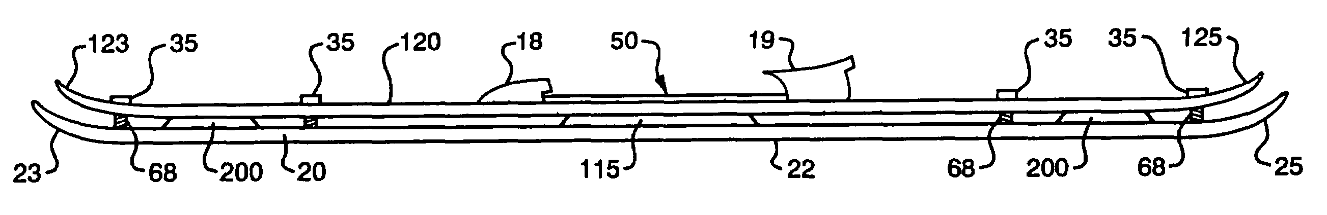
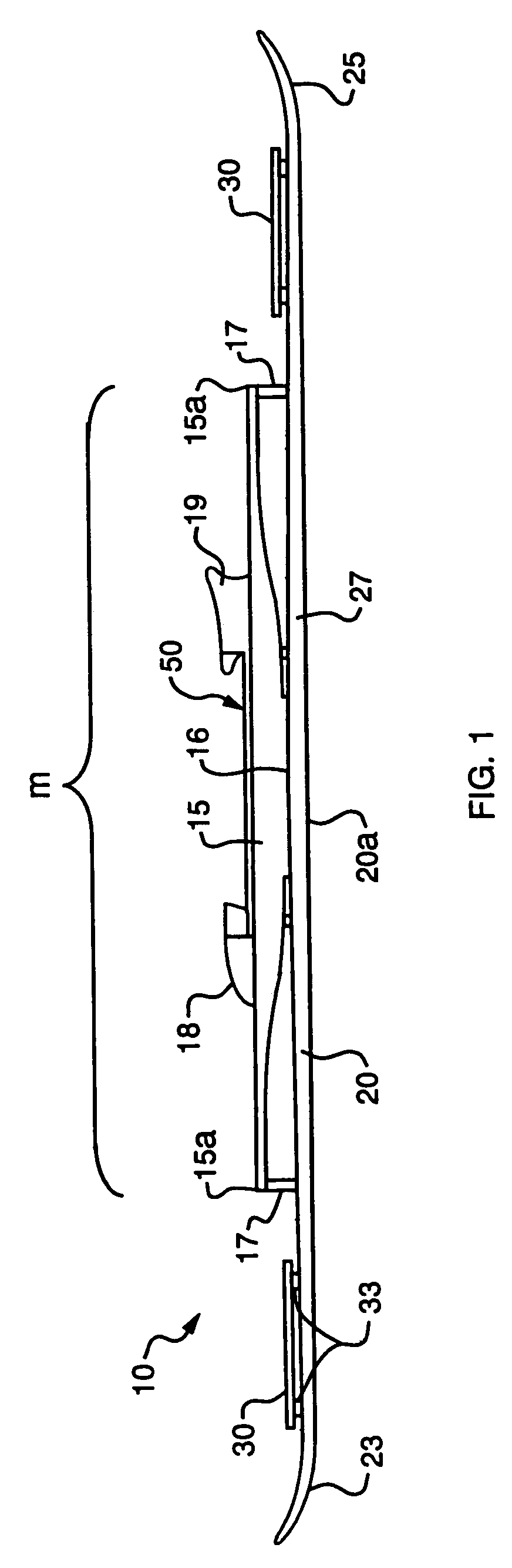
[0057]Referring now to the drawings, in which like reference numerals are used to refer to the same or similar elements, FIG. 1 shows a glider ski 10 of the invention. The glider ski 10 is one of a matched pair used for the relatively new skiing sport of glide-skiing, and the description herein should be interpreted to apply to the second ski in such a pair, except as noted. Typically, one glider ski 10 is equipped on each of a skier's feet using ski boots and bindings.

[0058]The glider ski 10 of the invention has increased turning ability and maneuverability as a result of improved flexibility achieved through the shape of the glider body 20 and additional components of the ski 10. The glider ski 10 has a bi-level design with a primary runner or glider body 20 defining a lower running surface 20a for contacting a skiing surface and a binding platform 15 for mounting a boot 40 above the glider body 20. Wings 30 are mounted above the level of the glider body 20 to provide a secondary ...


PUM


Abstract

A snow glider is provided having a design that facilitates gliding through snow rather than skidding. The snow glider may have a narrow waist width combined with an elevated binding assembly to promote positive engagement with a skiing surface during use. A method of skiing includes skiing downhill on a skiing surface using glider skis, wherein each ski has a ski base and a pair of edges extending along opposite sides of the base. While skiing downhill, the method of skiing also includes changing direction without skidding the skis on the skiing surface.

Description

CROSS-REFERENCE TO RELATED APPLICATIONS[0001]The present application is a continuation of U.S. application Ser. No. 10 / 286,643, filed Oct. 31, 2002 now U.S. Pat. No. 6,857,653, and titled “Glider Skis” which is hereby incorporated by reference in its entirety.FIELD AND BACKGROUND OF THE INVENTION[0002]The present invention relates generally to the field of ski construction and in particular to a new and useful ski apparatus capable of freely gliding on snow as opposed to skidding or scraping across the snow. The new ski has a uniquely narrow waist width, and a single- or double-bladed wing can be mounted above the primary ski for providing a secondary turning radius. The ski of the invention is substantially symmetrical with the narrow waist positioned midway along the length, and the tip and tail having similar shape and flexural characteristics. Additionally, the ski may include a bi-level suspension system with a boot binding assembly above the level of the running surface, and a...

Claims


Application Information

Patent Timeline
Patent Type & Authority Patents(United States)
IPC IPC(8): A63C5/04A63C5/048A63C5/06A63C9/00
CPCA63C5/0485A63C5/06A63C9/007A63C9/003A63C2203/46
Inventor WILSON, ANTON F.
Owner WILSON ANTON F
Why Eureka
Try Eureka