Cable actuator for lumbar support

a cable actuator and lumbar support technology, applied in the direction of shafts, mechanical control devices, controlling members, etc., can solve the problems of complicated coupling and uncoupling of the actuator and the cable system, and achieve the effect of preventing lateral displacement of the spindle and minimising the risk of the spindl

Inactive Publication Date: 2006-03-07
HENDERSONS IND PTY LTD
View PDF30 Cites 17 Cited by
  • Summary
  • Abstract
  • Description
  • Claims
  • Application Information

AI Technical Summary

Benefits of technology

[0022]The actuator of the present invention is able to use a thread pitch for each threaded portion and the respective nut which makes the actuator easier to operate, or to enable a greater range of movement for the adjustable device per revolution at a given thread pitch, or to provide a combination of these benefits. This is because the distance the adjustable device is moved is the aggregate of the longitudinal distance moved by the spindle relative to the housing, and the longitudinal distance moved by the second nut relative to the spindle. Thus, for the same given thread pitch for each threaded portion of the spindle, the distance through which the adjustable device is able to be moved is twice the distance moved by the spindle relative to the housing. Thus, there is greater scope for selection of the thread pitch for ease of operation, or to achieve a required movement of the adjustable device per revolution of the spindle, or a combination of these results. Also, while it generally is beneficial for the thread of each threaded portion of the spindle to have a common pitch, this is not necessary. That is, for each revolution of the spindle, the longitudinal distance moved by the second nut relative to the spindle may be greater or less than the longitudinal distance moved by the spindle.
[0038]The spindle may have a short unthreaded part of its length between adjacent ends of the threads of the first and second threaded sections. it is at this unthreaded part that it is convenient to provide abutment means which provides a sharply defined stop with the actuator in its “off” position. For this, the spindle may have a lateral projection at the unthreaded part, with the projection having an abutment face which makes surface to surface contact with an abutment face defined by the housing when the spindle reaches the “off” position. The abutment face of the spindle is somewhat radial and leads in the direction of helical advance of the spindle as it rotates and moves longitudinally towards the second end of the housing to its longitudinal location for the “off” position. The abutment face defined by the housing is similarly disposed but oppositely facing for good surface to surface contact between the abutment faces. While the respective abutment surfaces are substantially radially disposed, it is preferred that they are inclined slightly to the radial such that the outer edge of the spindle abutment surface leads in the direction of spindle rotation to the “off” position. This inclination brings the abutment surfaces into more positive face to face engagement in the event of excessive torque being applied to the spindle, thereby minimising the risk of the spindle abutment being able to be forced radially within the housing abutment and jamming of the actuator. This risk preferably is further reduced by the spindle having a spacer which projects laterally from the unthreaded part of the spindle, at a location diametrically opposed to the abutment face of the spindle. The spacer has a lateral extent such that it bears against the housing to prevent lateral displacement of the spindle sufficient to enable the spindle abutment to pass radially within the housing abutment.

Problems solved by technology

As with the barrel of Gowing et al, this complicates coupling and uncoupling of the actuator and cable system.

Method used


Image

  • Cable actuator for lumbar support
  • Cable actuator for lumbar support
  • Cable actuator for lumbar support

Examples


Embodiment Construction

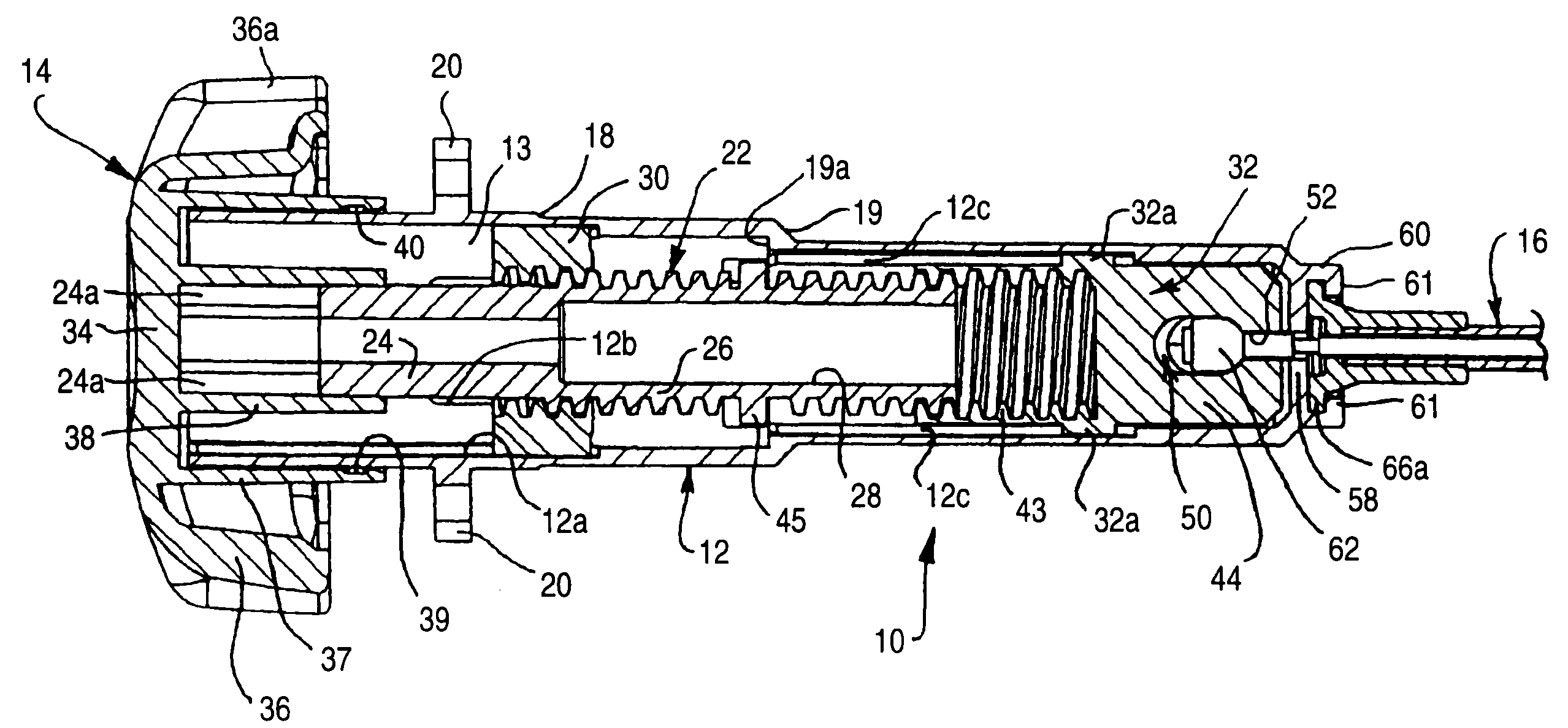
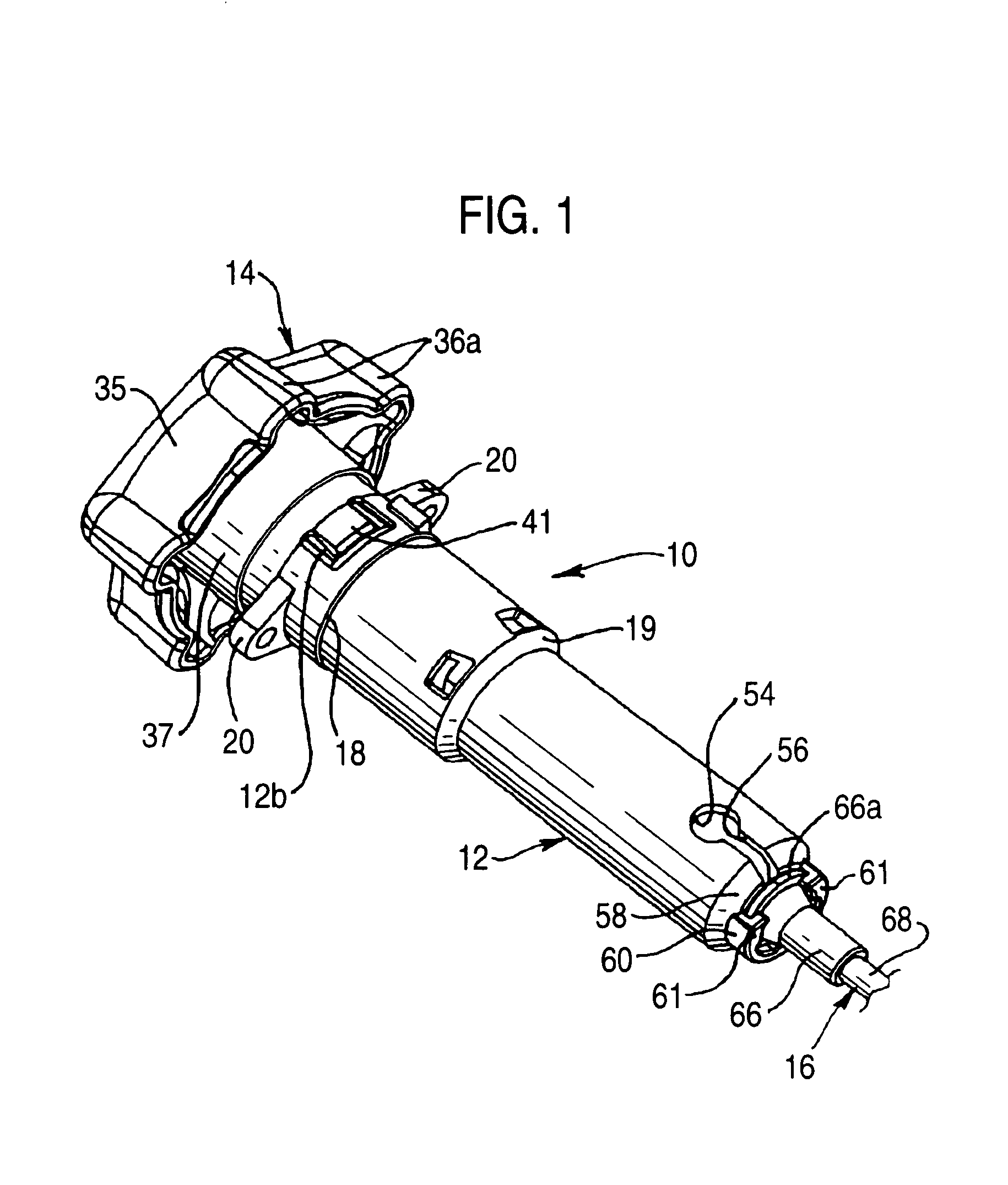
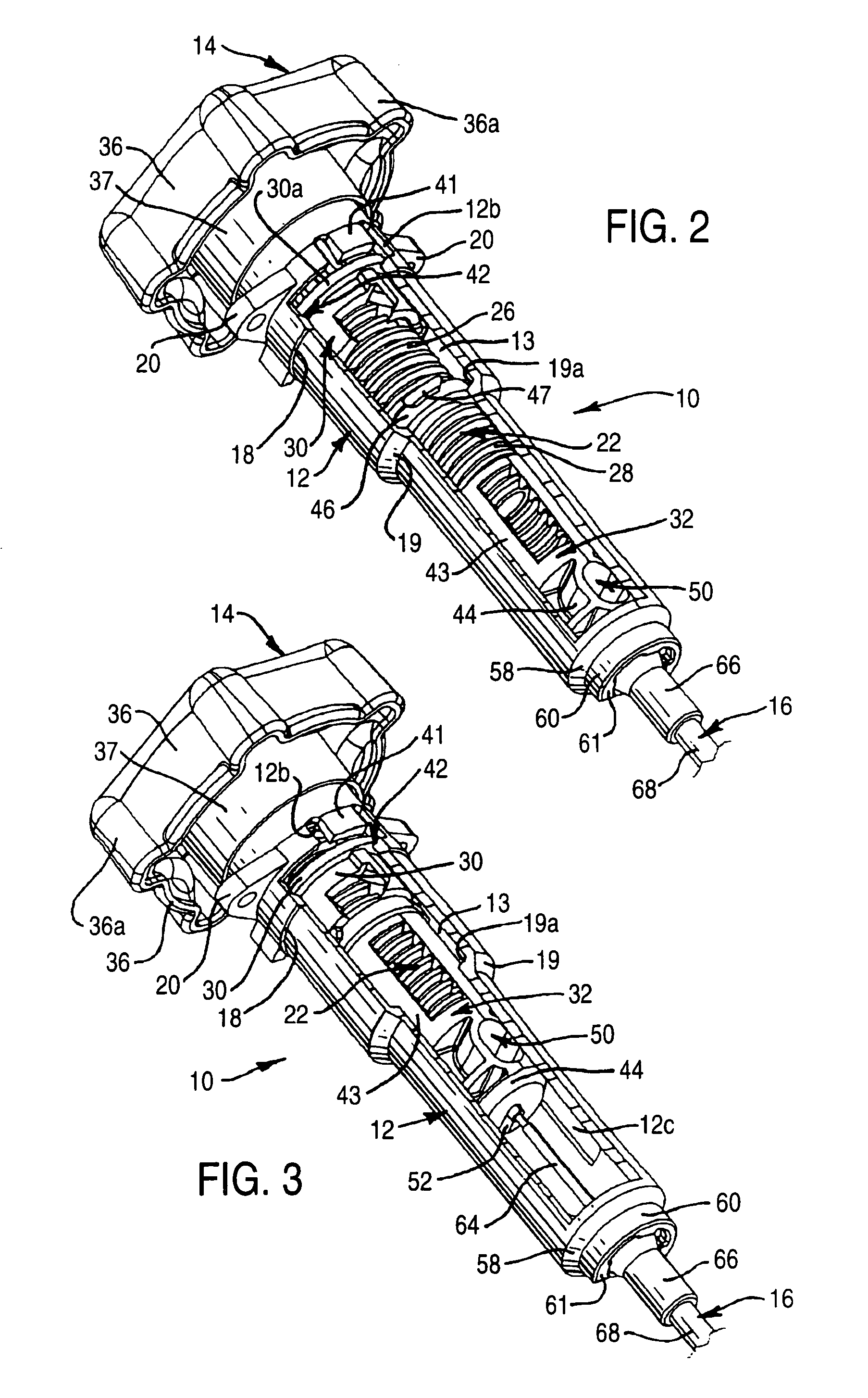
[0052]With reference to FIGS. 1 to 5, the actuator 10 shown therein has an elongate cylindrical housing 12, of circular cross-section, which has a handle 14 at one end and receives one end of a Bowden cable system 16 at the other end. From its first end, at which handle 14 is provided, housing 12 defines a passage 13 which has a maximum diameter through to a first step 18, an intermediate diameter from step 18 to a second step 19, and a minimum diameter from step 19 through to the second end through which system 16 is received. Adjacent to handle 14, housing 12 has two diametrically opposed lugs 20 by which actuator 10 is able to be mounted on a suitable support, such as a side frame of a vehicle seat. In the context of a vehicle seat, the end of system 16 remote from actuator 10 may be connected to an adjustable device to be adjusted or actuated through system 16 by actuator 10. The device at the remote end may, for example, be a lumbar support mounted within the seat-back.

[0053]As...


PUM


Abstract

The actuator has a housing with a longitudinal passage between a first end and an opening at a second end. A spindle, supported and moveable in the passage, has oppositely handed, first and second threaded portions each nearer a respective end of the housing. A first nut fixed relative to the housing is engaged with the first threaded portion. The spindle is rotated and moved relative to the first nut by a handle at the housing first end. A second nut fixed against rotation relative to the housing and engaged with the second threaded portion moves relative to and in the same direction as the spindle as the spindle rotates. The second nut is connectable through the opening to a device, and the spindle is rotatable by the handle for adjusting the device by movement of the spindle and the second nut.

Description

FIELD OF THE INVENTION[0001]This invention relates to an adjustment device, hereinafter referred to as an actuator, suitable for adjusting the operating position of another device, such as a lumbar support, either directly or by means of a Bowden cable system.BACKGROUND OF THE INVENTION[0002]Bowden cable systems are used in a wide variety of applications. One application is in adjusting a lumbar support built into a seat, such as a seat of an automotive vehicle. The Bowden cable system has a wire cable extending through a sleeve. The sleeve usually is held stationary at each end, enabling relative longitudinal movement between it and the cable. An actuator coupled to one end of the cable is able to move the cable reversibly, longitudinally through the sleeve, to enable reversible application of a force to a device, such as a lumbar support, coupled to the other end of the cable. The Bowden cable system is relatively inexpensive. Also, of importance in automotive applications, it is ...

Claims


Application Information

Patent Timeline
Patent Type & Authority Patents(United States)
IPC IPC(8): F16C1/12A47C3/025B60N2/66F16H25/20
CPCB60N2/66F16H25/20F16H2025/2059Y10T74/2084Y10T74/2042Y10T74/20426Y10T74/20402Y10T74/20732B60N2/6671
Inventor MACAULAY, RODNEY CRAIGHARRIS, WAYNE ANDREW
Owner HENDERSONS IND PTY LTD
Why Eureka
Try Eureka