Coupling device with configurable actuator

a coupling device and configurable actuator technology, applied in the direction of wrenches, medical science, surgery, etc., can solve the problems of increasing the risk of misassembly or malassembly, increasing the time and expense required for manufacturing tools incorporating these priors, and increasing the complexity of these mechanisms. , to achieve the effect of simple mechanism, convenient operation and reliable operation

Active Publication Date: 2011-04-19
WILSON GREATBATCH LTD
View PDF44 Cites 15 Cited by
  • Summary
  • Abstract
  • Description
  • Claims
  • Application Information

AI Technical Summary

Benefits of technology

[0008]The object of the invention is to provide a ratchet that is easy to operate and does so reliably.

Problems solved by technology

The complexity of these mechanisms increase the time and expense necessary for manufacturing tools incorporating these prior art ratcheting mechanisms.
One significant expense is the inventory expense, which requires that there be sufficient sets of replacement parts to support each model.
Another drawback is that as the number of parts which are similar in appearance (but not function) increases, the risk of misassembly or malassembly increases.
Such misassembly could cause a component or assembly to disassemble in a patient's body cavity during surgery.

Method used


Image

  • Coupling device with configurable actuator
  • Coupling device with configurable actuator
  • Coupling device with configurable actuator

Examples


Embodiment Construction

[0025]This invention has structural similarities to U.S. Pat. No. 6,817,458 to Gauthier, and WO 2004 / 096069, PCT / IB2004 / 001244, the contents of both of which are incorporated herein by reference and relied upon.

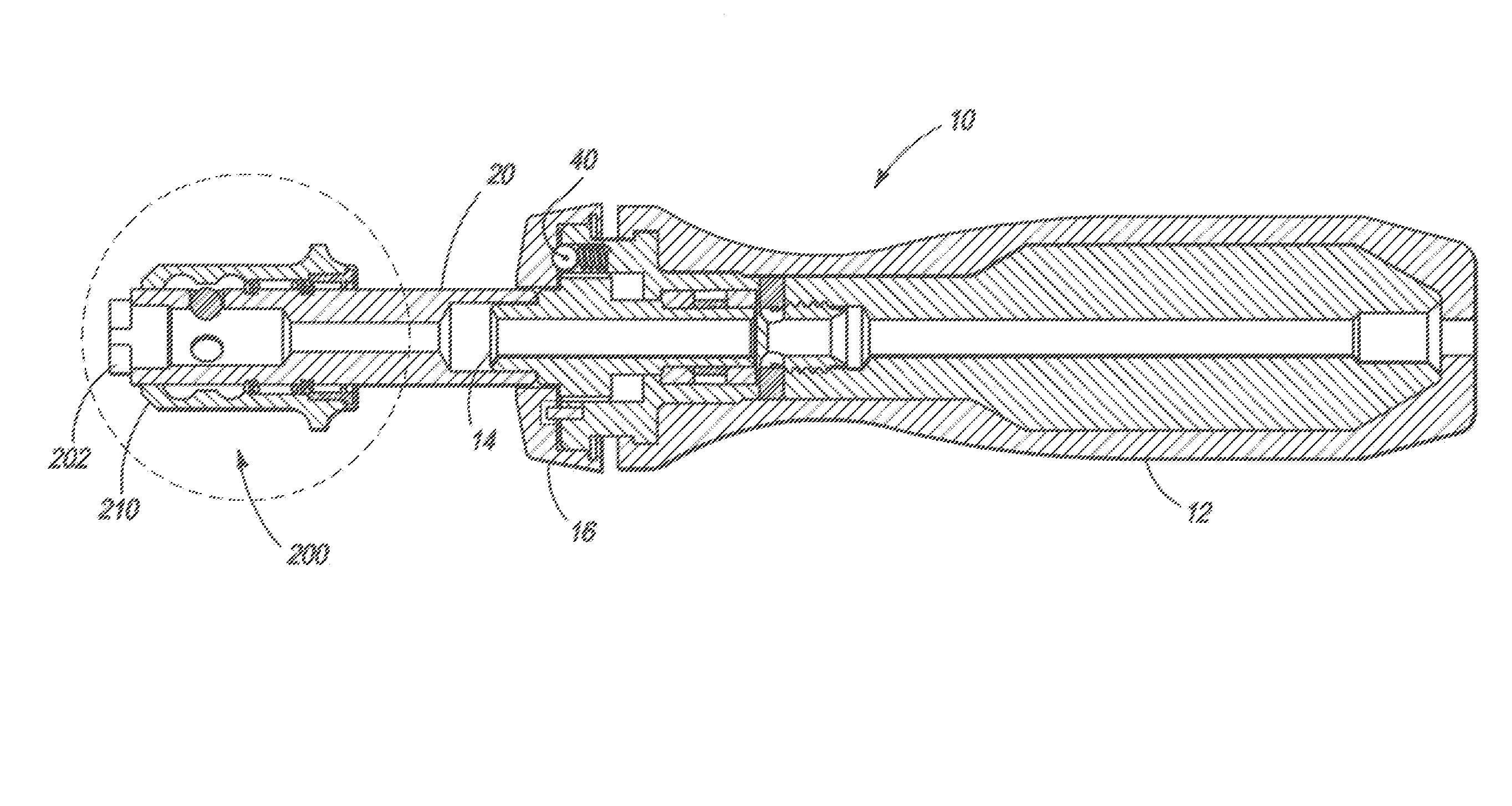
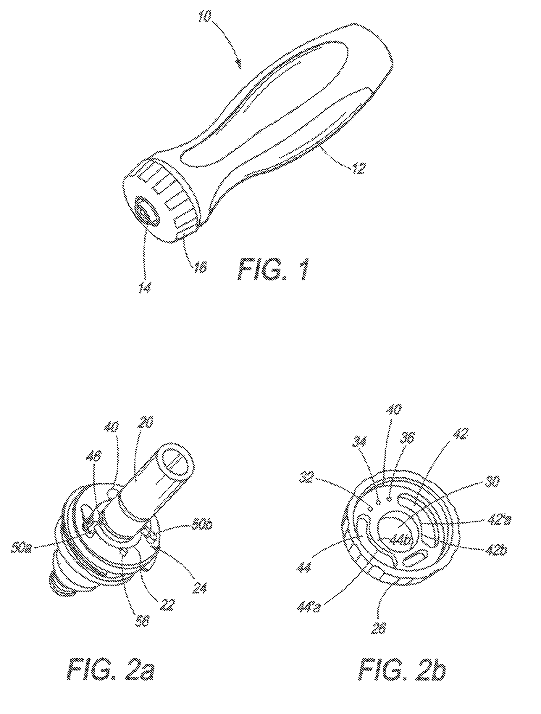
[0026]Referring now to FIG. 1, the ratchet handle 10 of the invention is shown, including essentially a handle portion 12, a coupling end 14, and a housing assembly 16 in which is disposed a drive spindle 20 having a toothed hub 22.

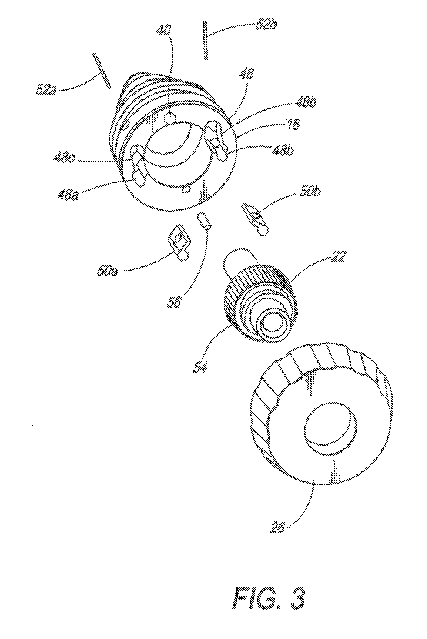
[0027]Referring now to FIGS. 2a and 2b, a ratchet mechanism 24 is disposed between the toothed hub 22 and the handle 12, in order to enable a user to selectively torque fasteners (not shown), in a desired direction dependent on the position of a reverser 26. The reverser 26 is a cap-shaped structure having an internal aperture 30 and position selection holes 32, 34 and 36 which pass through a wall 38 of the cap. A crest of a ball detent 40 in the housing 48 enters into such holes 32, 34, or 36 to retain the reverser 26 in the desired position (neut...


PUM


Abstract

A driving tool includes a shank, a sleeve, and a return spring disposed therebetween. The shank has a ball recess with a ball received therein. The shank has an interior interface adapted for receiving a tool bit. The ball recess substantially extends into the interior interface. The sleeve mounts on the shank to slide between limits. The sleeve has a first interior ball release recess followed by an interior ball lock surface and then a second interior ball release recess. The release recesses and surface are oriented with respect to the ball recess so as to permit selective displacement of the same over the ball recess to unlock the ball with movement in either direction. A return spring is disposed between the shank and the sleeve. The spring has a first and second end. One of the ends of the spring acts against a feature fixed with the shank and the other end of the spring acts against a feature fixed with the sleeve in a manner so as to permit selective displacement of the ball release recess and lock surface over the ball recess. The position of least spring potential energy is the position with the surface located just above the ball recess so as to tend to lock the ball into engagement with tool bit when the sleeve is in a rest position.

Description

CROSS REFERENCE TO RELATED APPLICATIONS[0001]This application is a continuation-in-part application of U.S. patent application Ser. No. 11 / 244,301, filed Oct. 5, 2005 now abandoned, entitled-RATCHET HANDLE, which claims priority to U.S. Provisional patent application Ser. No. 60 / 678,245, filed on May 5, 2005, the contents of which are incorporated herein by reference thereto and relied upon.BACKGROUND OF THE INVENTION[0002]This invention relates to drivers for rotary surgical cutting tools, and, more particularly, to drivers used in maxillo-facial, neuro, dental and orthopedic surgery, including reamer drivers.[0003]Screwdrivers, ratchet drivers, and other hand-held tools are often utilized to insert, remove and / or adjust fasteners attached to various items. The tool is used to rotate the fasteners into or out of apertures in the items to properly position the fasteners with respect to the items. In ratchet drivers, the rotation is controlled such that there is relatively free rotat...

Claims


Application Information

Patent Timeline
Patent Type & Authority Patents(United States)
IPC IPC(8): B25B13/46
CPCA61B17/1624B25B15/04A61B17/8875B25B13/463F16D41/16
Inventor BENNETT, JEFFREY
Owner WILSON GREATBATCH LTD
Why Eureka
Try Eureka