Tool

a tool and tool body technology, applied in the field of tools, can solve the problems of affecting the outer appearance of the finished receptacle, deteriorating the further operation contaminating the pressing surfaces of the tool parts, so as to achieve the effect of improving such a tool

Inactive Publication Date: 2011-04-19
SEDA SPA
View PDF3 Cites 3 Cited by
  • Summary
  • Abstract
  • Description
  • Claims
  • Application Information

AI Technical Summary

Benefits of technology

[0005]It is an object of the present invention to improve such a tool in that any contamination of the pressing surfaces and also delamination of the lower rim section of the receptacle is avoided.
[0012]To support the hardening of the corresponding gluing or sealing substance and to also prevent any heating of the tool, it is recommendable that inner and / or outer tool parts are cooled, in particular water-cooled.
[0017]It is possible that a corresponding groove is inclined with respect to a corresponding horizontal surface which means that the groove may, for example, extend over a corresponding height of the tool segment from one lateral end to the other lateral end of this segment. Of course, the corresponding groove may also end in a distance to the corresponding lateral ends of the segment and also in a distance to upper and lower surfaces of this segment. In case such an inclined groove is used, there is still the possibility that some amount of the gluing or sealing substance will be pressed to upper or lower edges of the corresponding rim sections and then be squeezed to the outside of this rim section to again contaminate the outer surface of the rim section or the tool. To better prevent such squeezing of the gluing or sealing substance, the groove may essentially extend in horizontal direction perpendicular to longitudinal axis of the receptacle. For such a groove arrangement, corresponding gluing or sealing substance will not be squeezed in direction of upper or lower edges of the rim section.
[0018]It is conceivable that at least the lower and upper grooves are arranged above each other in direction of longitudinal axis of the receptacle, such that both of those grooves may be used for accommodating any gluing or sealing substance that is squeezed by pressing the inner and outer tool parts together and to more securely prevent any squeezing of the gluing or sealing substance to the outside of the rim sections.
[0023]The corresponding pressing surfaces may extend parallel to longitudinal direction of the receptacle, which means parallel to the vertical direction. It may also be an advantage when those pressing surfaces of outer and inner tools are inversely inclined in this direction, wherein pressing surface of the inner tool part may in particular be inwardly inclined from lower to upper surfaces of the corresponding inner tool part.

Problems solved by technology

Consequently, the corresponding gluing or sealing substance may contaminate the pressing surfaces of the tool parts.
Such contamination may deteriorate the further operation of the tool parts and may also pollute the corresponding rim sections on the outer surfaces such that the outer appearance of the finished receptacle is negatively influenced.
Furthermore, the gluing or sealing substance in contact with the pressing surfaces may at least partly harden during the pressing of the rim sections, such that when removing the inner tool part to the retracted position, delamination of the rim sections is caused.
Such a delamination is generally detrimental in view of the sealing of the corresponding lower rim section that should be obtained by pressing the corresponding tool parts together with the lower rim sections therebetween.

Method used


Image

  • Tool
  • Tool
  • Tool

Examples


Embodiment Construction

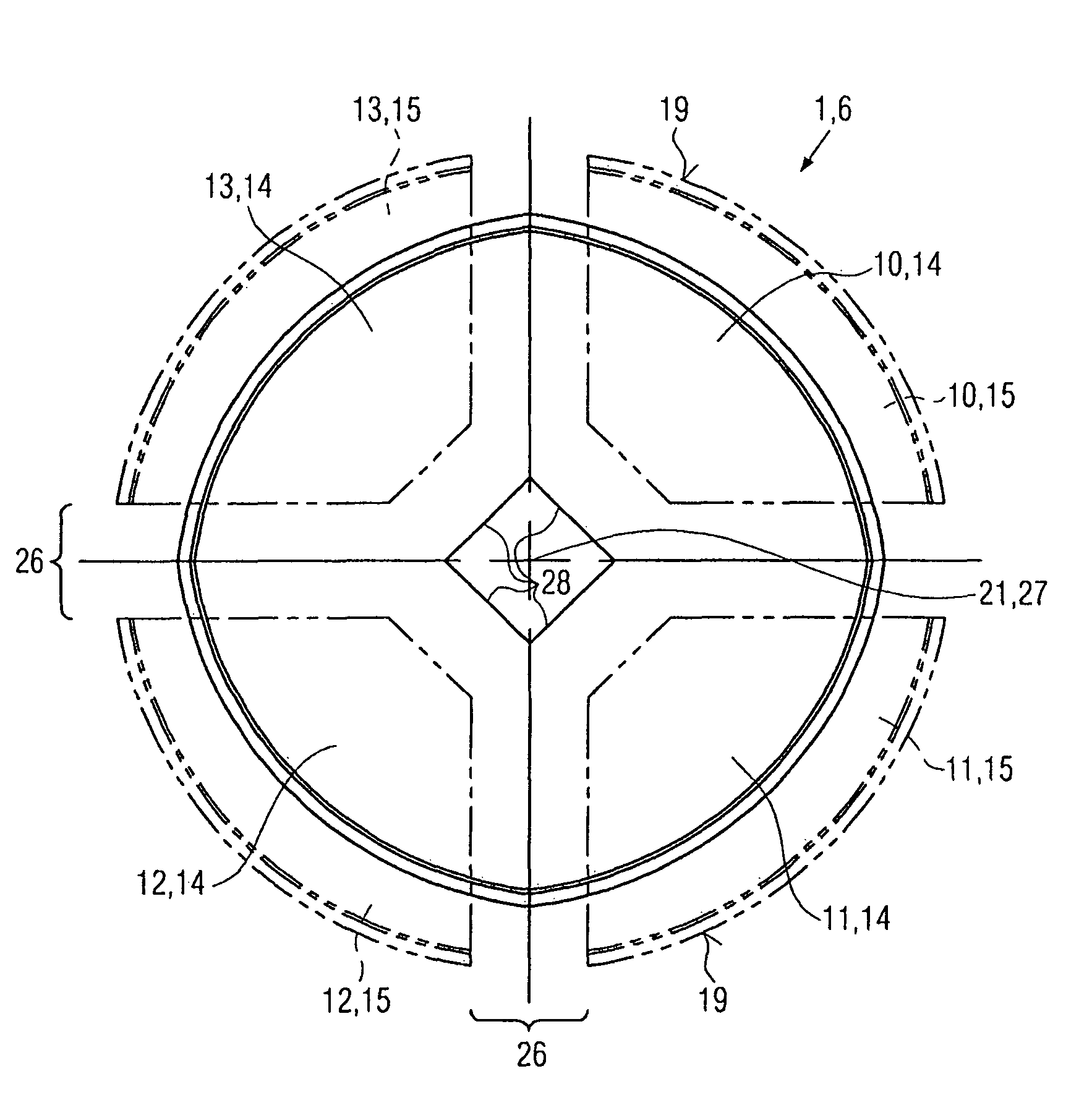
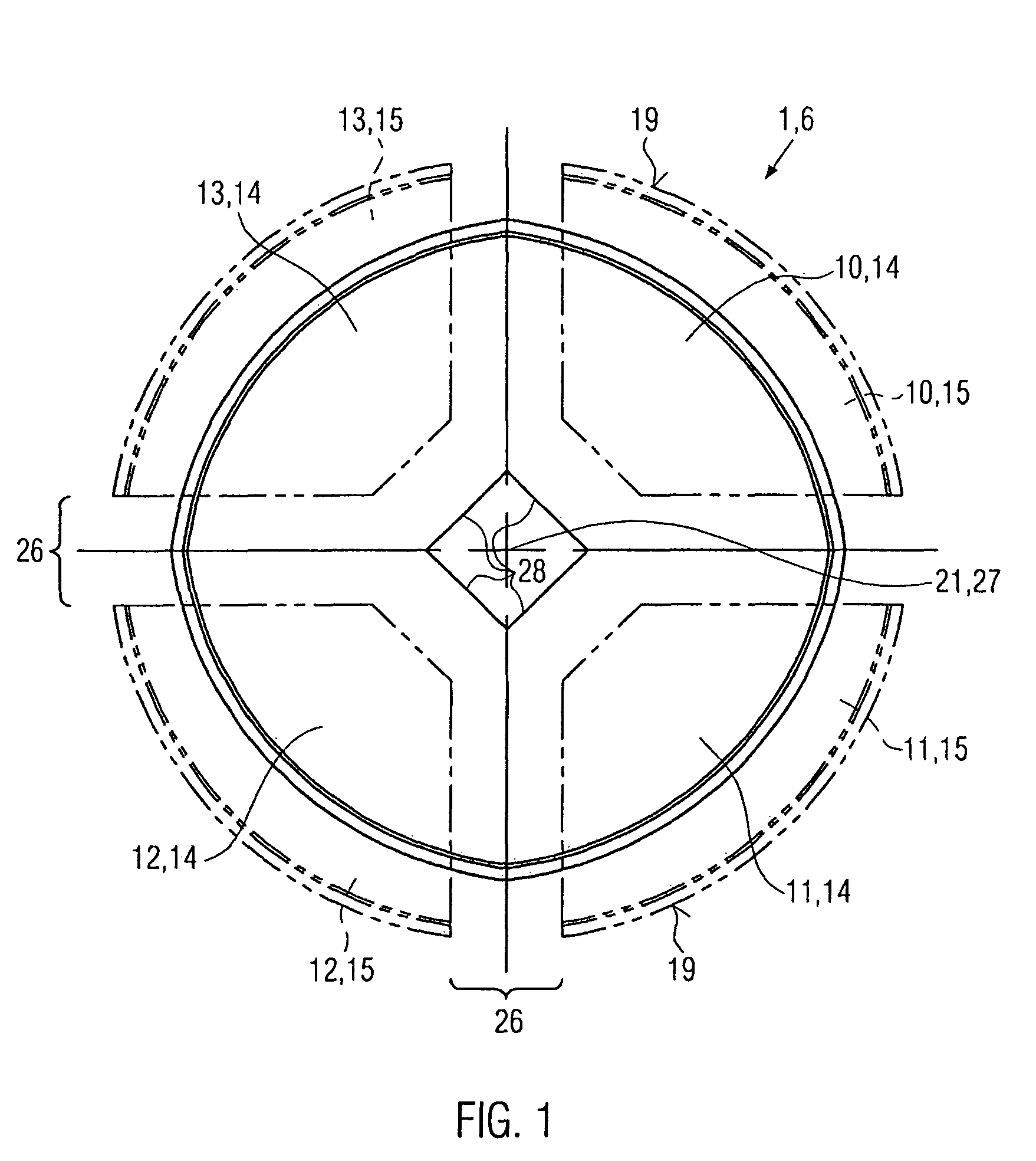
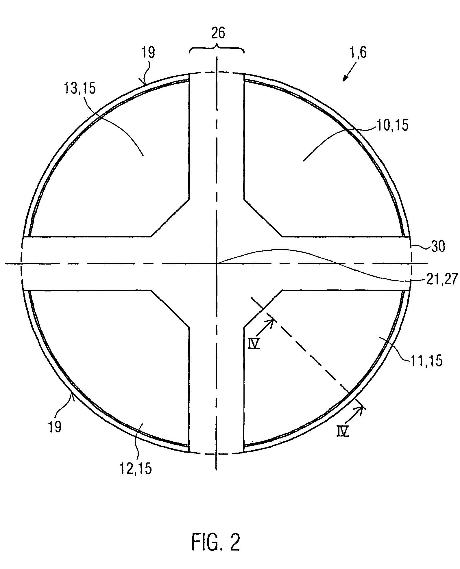
[0031]In FIG. 1 a top plane view of one embodiment of tool 1, and in particular of inner tool part 6, is illustrated. The inner tool part 6 is divided in four tool segments 10 to 13 that are arranged in their retracted positions 14. Each tool segment 10 to 13 has a cross section of a sector of a circle with a center angle of about 90°. The corresponding tool segments all have the same cross section and are all movable in radial direction, see the corresponding tool segments 10 to 13 in their pressing position 15 illustrated with chain dotted line in FIG. 1.

[0032]The corresponding tool segments are displaceable in horizontal direction, see also reference numeral 20 in FIG. 5, perpendicular to corresponding vertical direction 27 which corresponds to a longitudinal axis 21 of a corresponding receptacle 8, see again FIG. 5.

[0033]Corresponding means for moving the tool segments are not illustrated in FIG. 1.

[0034]In their pressing position 15, the corresponding tool segments 10 to 13 are...


PUM

PropertyMeasurementUnit
angleaaaaaaaaaa
center angleaaaaaaaaaa
period of timeaaaaaaaaaa

Abstract

A tool for pressing lower rim section of a receptacle wall and a receptacle bottom comprises an inner tool part and an outer tool part. The outer tool part essentially surrounds the receptacle at its lower end. The inner tool part comprises tool segments that are moveable relative to the outer tool part between a retracted and a pressing position, wherein in the pressing position the lower rim sections are pressed together by opposed pressing surfaces of outer tool part and inner tool part. To avoid any contamination of the pressing surfaces and also delamination of the lower rim section of the receptacle, at least one groove is formed in the pressing surface of the tool segment and / or of the outer tool part.

Description

RELATED APPLICATION[0001]Priority is claimed under 35 U.S.C. §119 to German Patent Application No. 20 2005 019 396.8 filed on Dec. 12, 2005. The entire contents of the priority application are incorporated herein by reference.BACKGROUND OF THE INVENTION[0002]For the production of cup-shaped receptacles comprising at least a receptacle wall and a receptacle bottom, a tool is used for pressing lower rim sections of receptacle wall and receptacle bottom together. The tool has an inner tool part and an outer tool part. The outer tool part essentially surrounds the receptacle at its lower end and is arranged outside of the receptacle. The inner tool part comprises a number of tool segments that are movable relative to the outer tool part between a retracted and a pressing position. In the retracted position it is possible to arrange corresponding rim sections between outer tool part and inner tool part. Then, the tool segments are moved in direction to the outer tool part and when the pr...

Claims


Application Information

Patent Timeline
Patent Type & Authority Patents(United States)
IPC IPC(8): B32B37/00
CPCB31B1/60B31B17/00Y10T29/53B31B2217/082B31B2201/60B31B50/00B31B50/60B31B50/64B31B2105/0022
Inventor D'AMATO, GIANFRANCO
Owner SEDA SPA
Why Eureka
Try Eureka