Agricultural combine active spreader having a triangular nose divider

a spreader and active technology, applied in the field of active spreaders, can solve the problems of uneven crop residue distribution, loss of straw and other residues through gaps in the spreader area, and a portion of crop residues may be engaged, so as to improve the spread width and distribution

a spreader and active technology, applied in the field of active spreaders, can solve the problems of uneven crop residue distribution, loss of straw and other residues through gaps in the spreader area, and a portion of crop residues may be engaged, so as to improve the spread width and distribution

US7927200B2Inactive Publication Date: 2011-04-19BLUE LEAF I P INC

Image

  • Agricultural combine active spreader having a triangular nose divider
  • Agricultural combine active spreader having a triangular nose divider
  • Agricultural combine active spreader having a triangular nose divider

Examples


Embodiment Construction

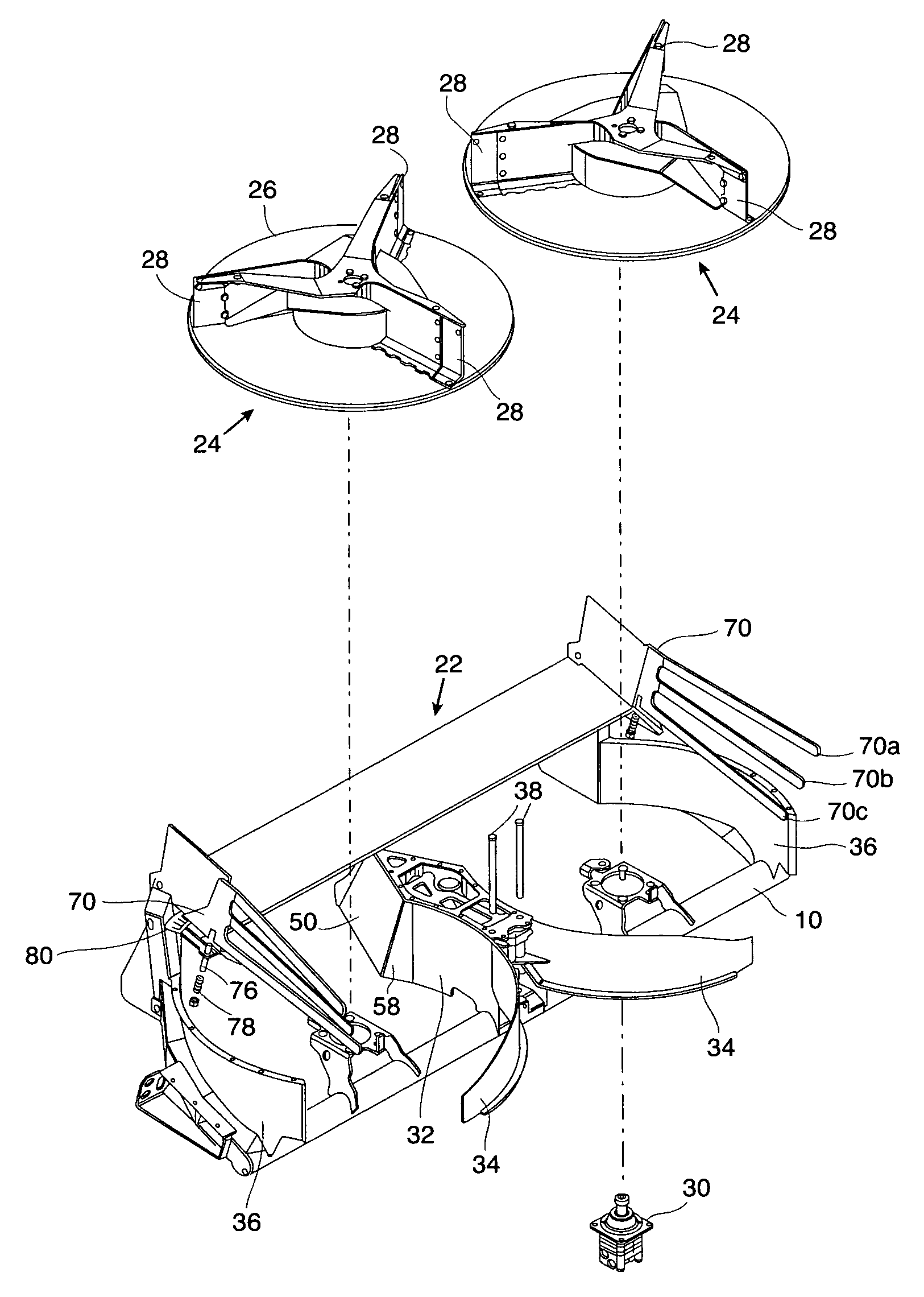
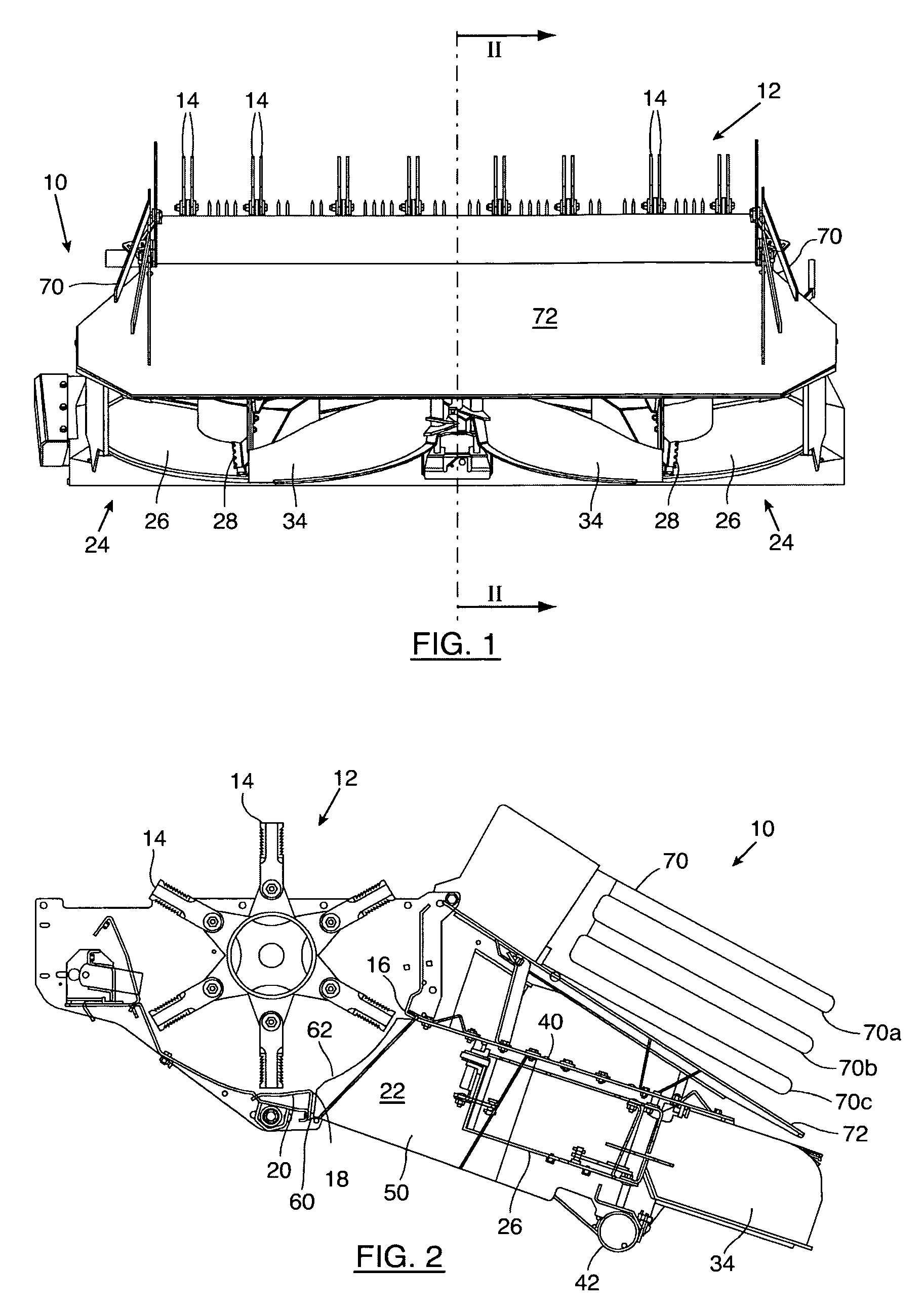
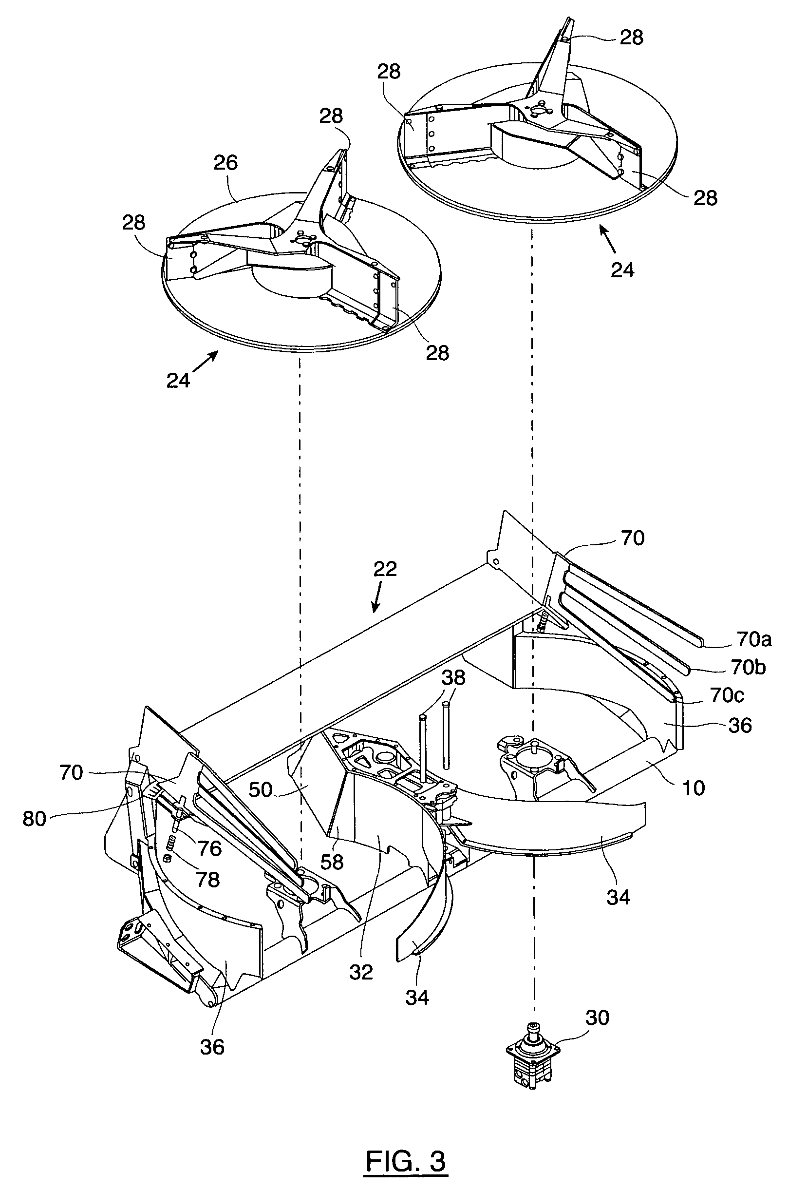
[0028]Straw, stalks, corn cobs and other crop residue and trash that has been separated from the grain of the crops by a threshing mechanism inside an agricultural combine can be spread out on the field by a spreader 10. The straw, stalks and the like are propelled rearwardly by transversal rotating beaters or the like from the threshing mechanism to a horizontal spreader 10 for spreading, and optionally chopping thereby, all in the well known manner. The rotating beater may comprise a straw chopper 12 equipped with ranges of knives 14, which are rotated for chopping the crop residue and propelling it to the entrance of the spreader 10.

[0029]The chopper outlet is defined between upper and lower borders 16, 18, which extend the full width of the chopper body. The gap between the chopper outlet upper border and the entrance of the active spreader 10 should be minimal to prevent uncontrolled whirls and consequent loss of residue. A straw guidance plate 20 mounted under an upward angle ...


PUM


Abstract

An active crop residue spreader for an agricultural combine including two horizontal rotor impellers for guiding and uniformly distributing the crop residue on a field, a triangular nose divider with a pyramidal shape which is wider at the base and an extension near or into the chopper. The spreader further comprises a straw guiding plate provided with specially shaped rakes on each side of the guiding plate.

Description

CROSS REFERENCE TO RELATED APPLICATIONS[0001]This Patent Application claims priority under 35 U.S.C. §119 to EP 08.158.965.7, filed on Jun. 25, 2008 titled, “Active spreader for an agricultural combine” and having Daniël M. G. Van Overschelde, Luc Alexa Yde, Frank R. G. Duquesne, Yvan C. C. Vandergucht and Wim S. O. Declercq as inventors. The full disclosure of EP 08.158.965.7 is hereby fully incorporated herein by reference.FIELD OF THE INVENTION[0002]The invention relates to an active spreader for controlled spreading of a flow of straw and other crop residue on a field from which the crop was harvested.BACKGROUND OF THE INVENTION[0003]Currently, combines typically include crop residue spreader apparatus for disposing of straw and other residue separated from the harvested crop onto the field from which the crop was harvested. In addition, some combines have a chaff spreader for spreading chaff residue separated from the grain by the cleaning apparatus or system onto the field. In...

Claims


Application Information

Patent Timeline
19 Apr 2011
Publication
US7927200B2
IPC
A01F12/40
CPC
A01F12/40; A01D41/1243
Inventors
VAN OVERSCHELDE, DANIEL M. G.; YDE, LUC A.