Method and system for determining an optimized artificial impedance surface

Active Publication Date: 2011-04-19
HRL LAB
View PDF27 Cites 29 Cited by
  • Summary
  • Abstract
  • Description
  • Claims
  • Application Information

AI Technical Summary

Benefits of technology

[0011]From the calculated artificial impedance pattern, an actual surface wave profile produced on the impedance surface by the artificial impedance pattern, and an actual far field radiation pattern produced by the actual surface wave profile are calculated. Calculating the actual surface wave profile produced requires use of an electromagnetic simulation tool capable of taking into account the effects of edge scattering from a surface with a varying impedance boundary condition and generally arbitrary surface geometry. A simulator and calculation method capable performing the required calculations is described in U.S. Pat. No. 6,847,925 to Ottusch et al., incorporated herein by reference in its entirety.
[0012]B

Problems solved by technology

Using only an assumed surface wave profile therefore results in less than optimal efficiency of conversion from excitation input power to the desired far field radiation pattern.

Method used


Image

  • Method and system for determining an optimized artificial impedance surface
  • Method and system for determining an optimized artificial impedance surface
  • Method and system for determining an optimized artificial impedance surface

Examples


Embodiment Construction

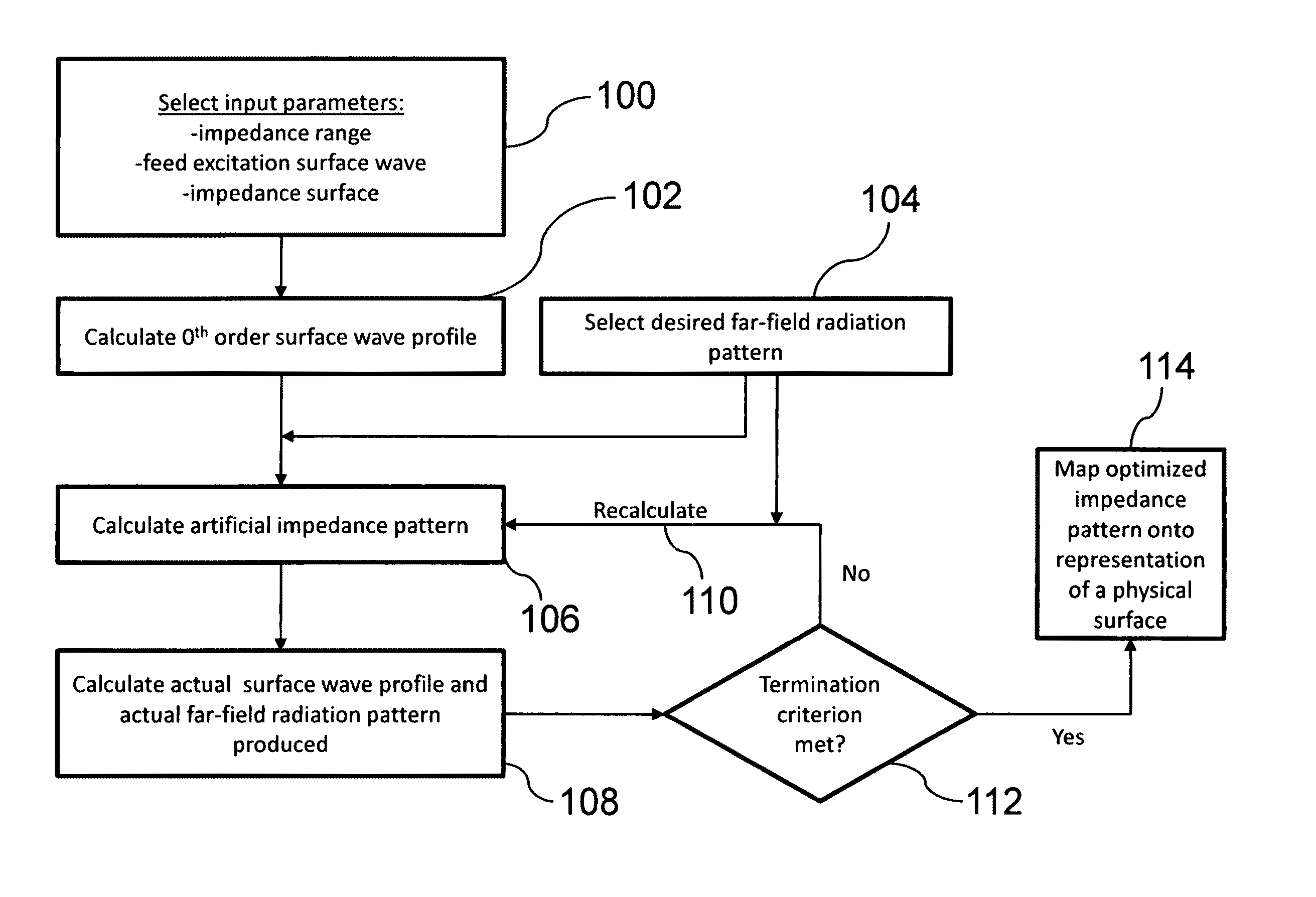
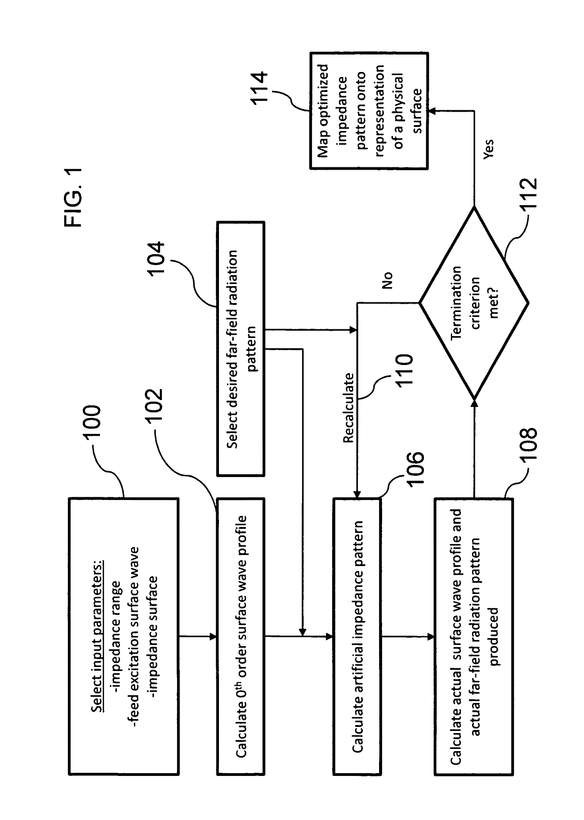
[0047]The present invention relates to a method for determining an artificial impedance surface, and in particular a method for determining an optimized artificial impedance surface by calculating actual surface wave profiles supported on the impedance surface. The following description is presented to enable one of ordinary skill in the art to make and use the invention and to incorporate it in the context of particular applications. Various modifications, as well as a variety of uses in different applications will be readily apparent to those skilled in the art, and the general principles defined herein may be applied to a wide range of embodiments. Thus, the present invention is not intended to be limited to the embodiments presented, but is to be accorded the widest scope consistent with the principles and novel features disclosed herein.

[0048]In the following detailed description, numerous specific details are set forth in order to provide a more thorough understanding of the p...


PUM


Abstract

A method and system for determining an optimized artificial impedance surface is disclosed. An artificial impedance pattern is calculated on an impedance surface using an optical holographic technique given an assumed surface wave profile and a desired far field radiation pattern. Then, an actual surface wave profile produced on the impedance surface from the artificial impedance pattern, and an actual far field radiation pattern produced by the actual surface wave profile are calculated. An optimized artificial impedance pattern is then calculated by iteratively re-calculating the artificial impedance pattern from the actual surface wave profile and the desired far field radiation pattern. An artificial impedance surface is determined by mapping the optimized artificial impedance pattern onto a representation of a physical surface.

Description

BACKGROUND OF THE INVENTION[0001](1) Field of Invention[0002]The present invention relates to a method for determining an artificial impedance surface and, in particular, to a method for determining an optimized artificial impedance surface by calculating actual surface wave profiles supported on the impedance surface.[0003](2) Description of Related Art[0004]The closest related art for the creation of artificial impedance surfaces is disclosed in U.S. Pat. No. 7,218,281 to Sievenpiper et al., herein incorporated by reference (hereinafter “Sievenpiper et al.”). Sievenpiper et al. discloses how to create an artificial impedance surface using metal patterning in order to scatter a given excitation into a desired far field radiation pattern. This method of creating the surface patterning relies on a radiofrequency holographic technique, where the impedance pattern is determined from the interference of a surface wave and the desired outgoing wave. Sievenpiper et al. uses only assumed s...

Claims


Application Information

Patent Timeline
IPC IPC(8): G01B11/02H01Q15/24H01Q15/02
CPCH01Q15/0046
Inventor FONG, BRYAN H.COLBURN, JOSEPH S.OTTUSCH, JOHNSIEVENPIPER, DANIEL F.VISHER, JOHN L.
Owner HRL LAB
Why Eureka
Try Eureka