

Substrate transport device and substrate processing apparatus
a technology for transporting devices and substrates, applied in transportation and packaging, electric devices, conveyor parts, etc., can solve problems such as easy sliding of substrates on the arm
- Summary
- Abstract
- Description
- Claims
- Application Information
AI Technical Summary
Benefits of technology
Problems solved by technology
Method used
Image

Examples
first embodiment
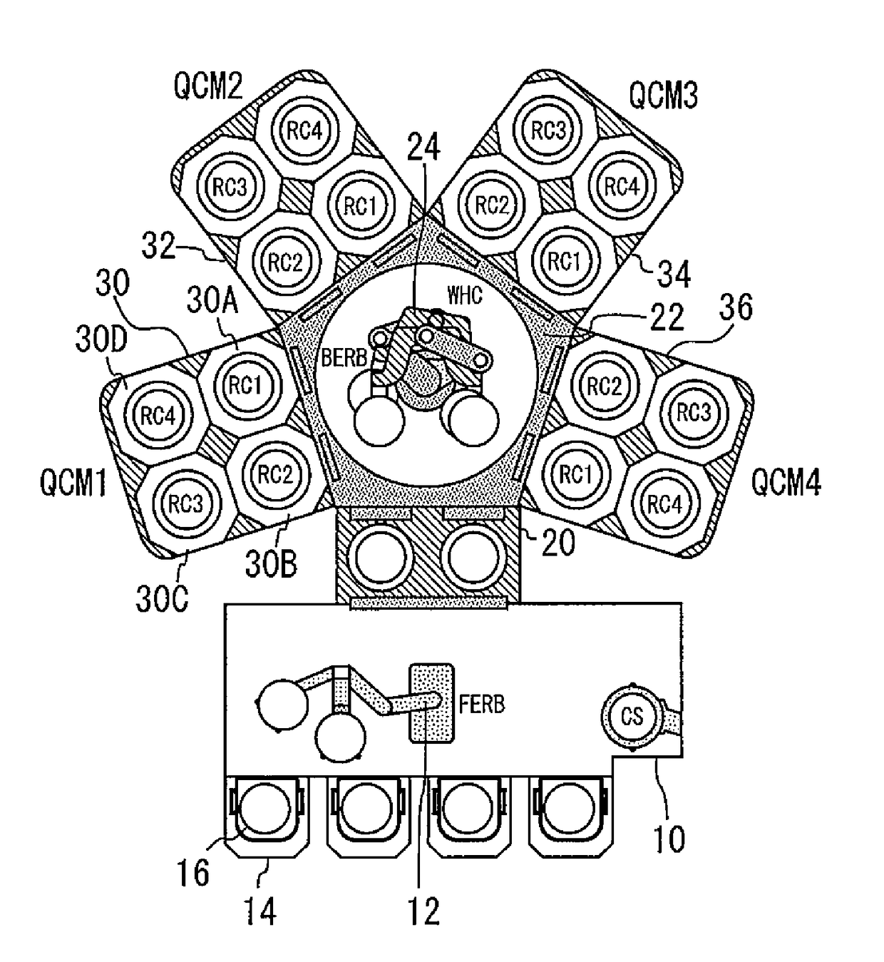
[0025]FIG. 1 is a plan view of a substrate processing apparatus including a substrate transport device according to a first embodiment of the present invention. This substrate processing apparatus is provided with a transport chamber 10. The interior of the transport chamber 10 is maintained generally at atmospheric pressure. The transport chamber is called an equipment front end module (EFEM).
[0026]A robot arm 12 for transporting substrates is provided in the transport chamber 10. This robot arm 12 is called a Front End Robot (FERB). The robot arm 12 includes, for example, an upper arm and a lower arm and is, therefore, capable of transporting two substrates separately.
[0027]A load port 14 is attached to a side of the transport chamber 10. The load port 14 is a table on which a case 16 (FOUP) containing substrates is mounted. The robot arm 12 draws out a substrate from the case 16 or puts a substrate in the case 16.
[0028]A load lock chamber 20 is attached to another side of the tra...
second embodiment
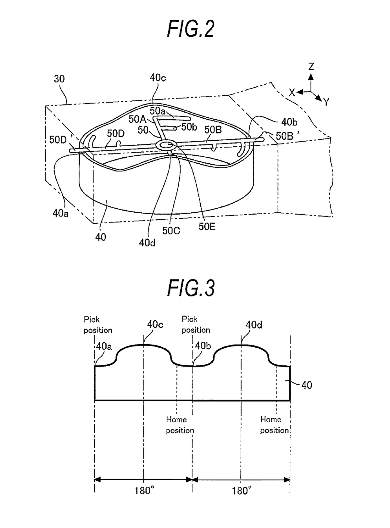
[0063]FIG. 9 is a sectional view of a portion of the substrate transport device according to the second embodiment. A wheel 90 is attached to a lower side of a rotation arm 50D. The wheel 90 is fixed to the rotation arm 50D by a shaft part 92 passing through a center of the wheel 90. The rotation arm 50D contacts the upper surface of the cylindrical supporting part 40 by means of the wheel 90. With rotation of the rotation arm, the wheel 90 slides on the upper surface of the cylindrical supporting part 40.
[0064]FIG. 9 shows a state where the wheel 90 and the first upper surface 40a contact each other. FIG. 10 shows a state where the wheel 90 and the second upper surface 40c contact each other. FIG. 11 is a side view of the wheel 90. The wheel 90 runs on the sloped upper surface of the cylindrical supporting part 40. The provision of the wheel 90 enables reducing friction in comparison with the case where the rotation arm and the cylindrical supporting part 40 directly contact each o...
third embodiment
[0065]FIG. 12 is a plan view of a rotation arm 50A according to the third embodiment. Projections 100 which are convex in the direction of being away from the shaft (the direction of an arrow) as viewed in plan are formed on an upper surface of the rotation arm 50A. The projections 100 contact a substrate.
[0066]The projections 100 are provided for the purpose of preventing the substrate from moving toward the shaft when the rotation arm is inclined. Since the projections 100 have the shape convex in the direction of centrifugal force of the substrate as viewed in plan, the projections 100 are effective in preventing the substrate from sliding toward the shaft. It is preferable that the projections 100 thus formed be provided on all rotation arms. A suitable combination of the features of the substrate transport devices and the substrate processing apparatuses according to the embodiments described above may be made and used as desired.
[0067]According to the present invention, the ar...
PUM
 Abstract
Description
Claims
Application Information