Large-scale adaptive surface sensor arrays

a sensor array and large-scale technology, applied in the direction of radiating elements, electromagnetic wave system, resonance antenna, etc., can solve the problems of increasing the number and/or complexity of the actuator array on the surface, and requiring a large number of actuators. the effect of structural range of motion and/or actuator density, complex acquisition and tracking

Active Publication Date: 2007-12-11
HRL LAB
View PDF201 Cites 153 Cited by
  • Summary
  • Abstract
  • Description
  • Claims
  • Application Information

AI Technical Summary

Problems solved by technology

The implementation of a system of large-scale actuator arrays and sensors for the contour and control of surfaces for space or other applications, presents significant challenges.
In either case, increasing the number and / or complexity of the actuators on the surface will likely be required.
The higher number and greater functionality of the actuator array, complicates the corresponding power and control network.
This can be accomplished without the use of power and control wires which complicate the architecture, add mass, and may interfere with the deployment and function of the structure (if they bind or tangle).
However, this technical can be inefficient if the transmit beam angle is large and the broadcast frequency is high.
In this case, the power available to the actuator is very low due to the small size of the receive antenna compared to the beam footprint at the surface.
Much of the transmitted power is therefore lost.
Another potential problem is that the radiated energy may interfere with sensitive systems on or near the platform or inadvertently reflected off the surface and interfere with the platform's mission.
This process often requires complex and precise gimballing mechanisms and tracking systems.
However, actuator options with this method are limited and possibly prohibitive.
Also, as with all focused beam concepts, more complex acquisition and tracking may be required as structural range-of-motion and / or actuator density increases.

Method used


Image

  • Large-scale adaptive surface sensor arrays
  • Large-scale adaptive surface sensor arrays
  • Large-scale adaptive surface sensor arrays

Examples


Embodiment Construction

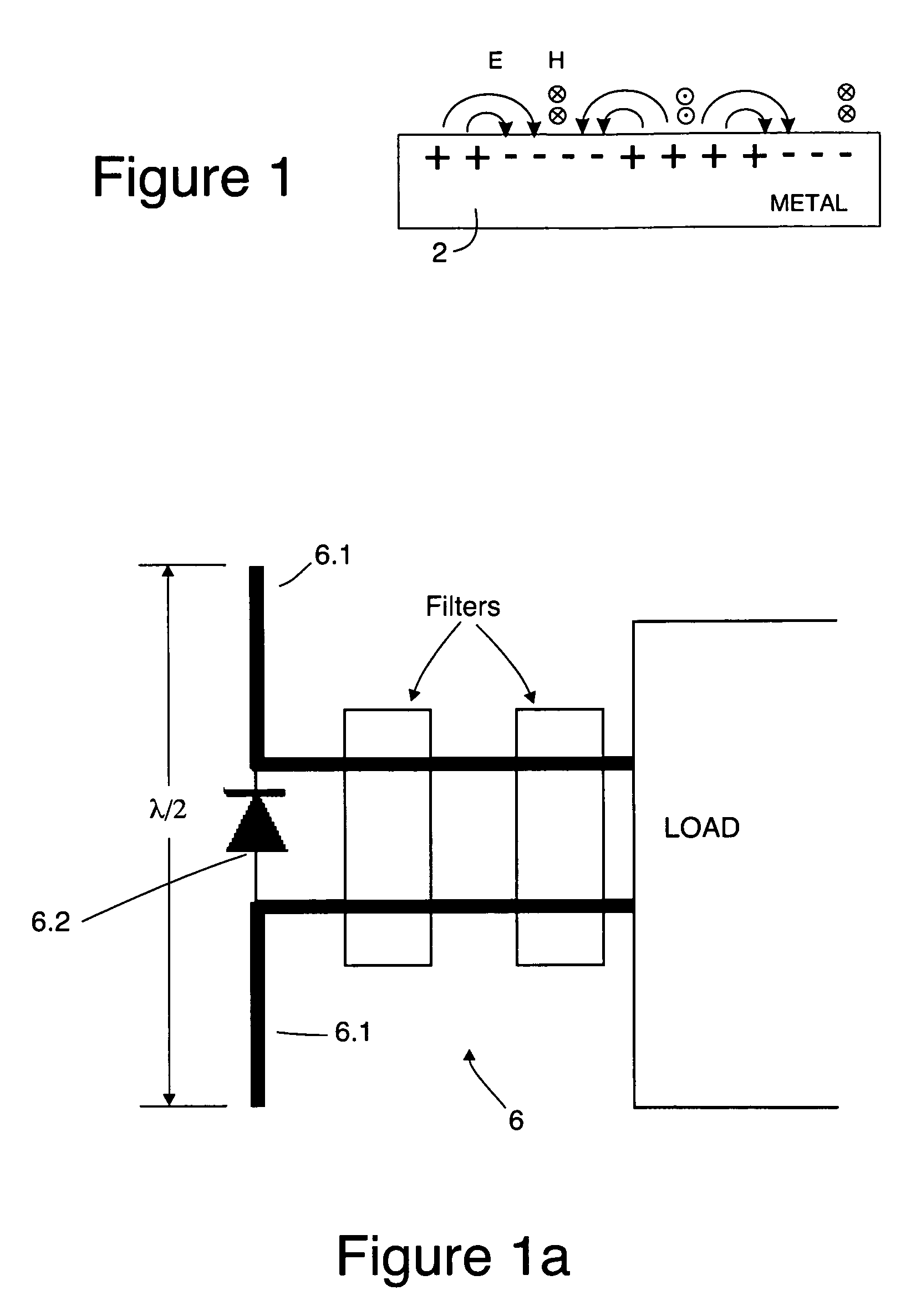
[0052]The term “metasurface” as used herein is intended to refer to a surface whose electro-magnetic properties are determined by its structure and / or geometry rather than by its constituent material properties. A frequency selective surface (FSS) is one type of a metasurface.

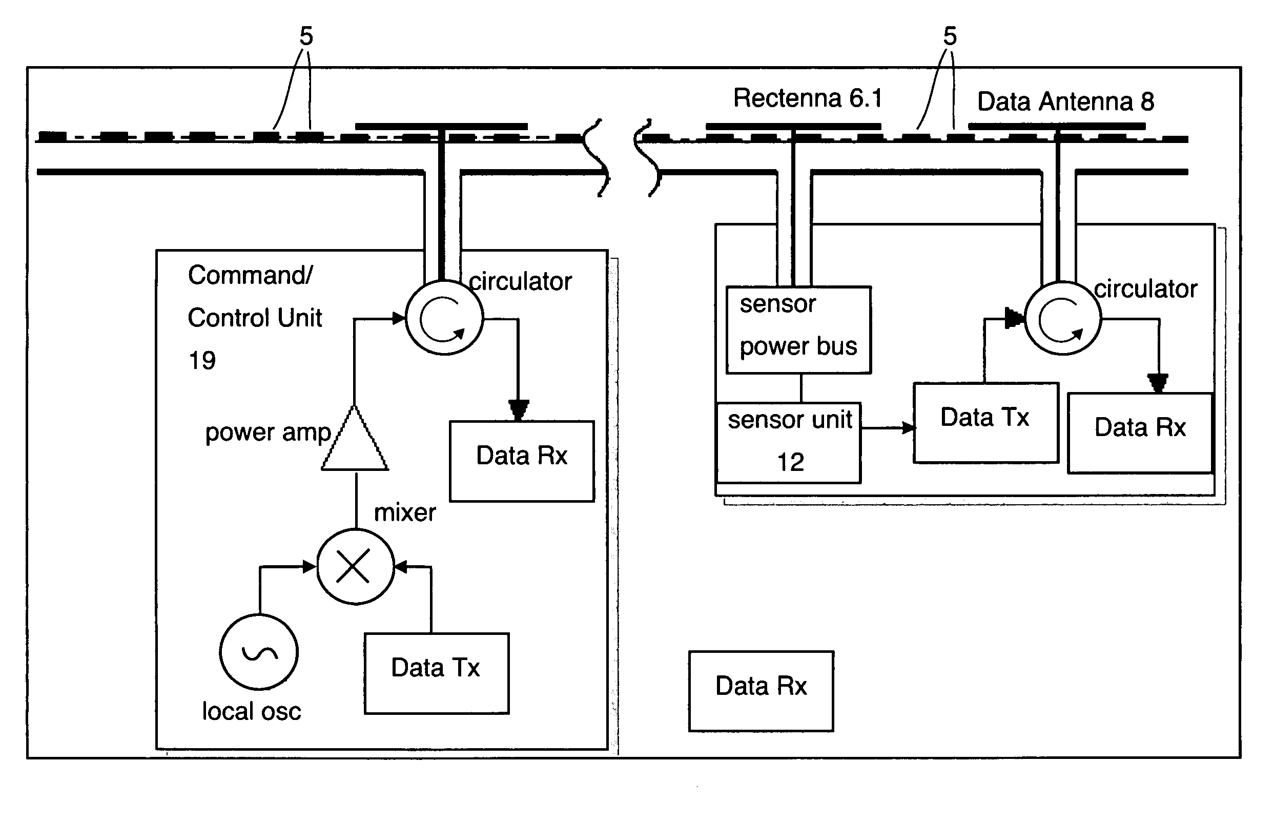
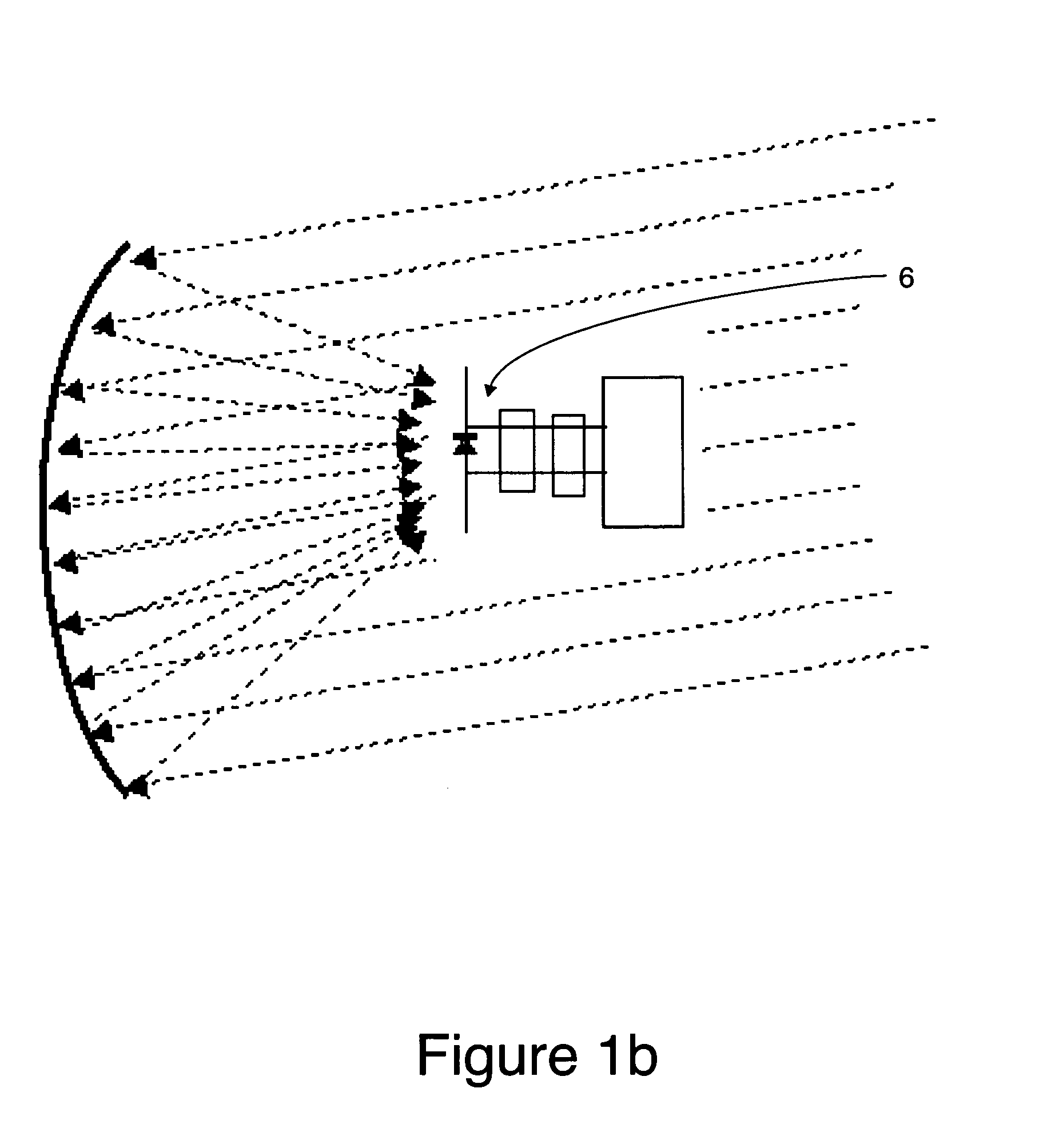
[0053]In one embodiment, the present invention includes a meta-surface (a specially designed textured surface 9—see, for example, FIG. 2a) that supports localized electromagnetic surface wave tightly bound to its surface, one or more surface-wave transmitters and an array of surface wave receivers. In one application, the transmitter is used in conjunction with a central control module that modulates surface-wave carriers with a power transmission signal and data signals. A single transmitter or a plurality of separate transmitters can be used to transmit the power and data waves. Meanwhile the receivers are connected to an array of actuators, sensors, or a network of other devices, that are powered preferably ...


PUM


Abstract

An adaptive surface has a dielectric surface with a repeating pattern of electrically conductive structures disposed thereon or therein, the dielectric surface in combination with repeating pattern of electrically conductive structures forming a metasurface for binding surface waves thereto. A plurality of actuators on the dielectric surface alter the shape of the metasurface in response to control signals. A plurality of sensors on the dielectric surface for measuring a desired parameter and converting it to data. A plurality of rectennae disposed on the dielectric surface for providing electrical power to said actuators and to said sensors. A plurality of data antennas are disposed on or in the dielectric surface, the data antennas being coupled with data receivers and data transmitters for receiving data from an external source for controlling the actuators and for transmitting data from said sensors to an external receiver.

Description

CROSS REFERENCE TO A RELATED APPLICATION[0001]This application is related to U.S. patent application Ser. No. 10 / 944,032 filed 17 Sep. 2004 entitled “Large Aperture Rectenna Based on Planar Lens Structures”, which application is assigned to the assignee of the present application. The disclosure of U.S. patent application Ser. No. 10 / 944,032 is hereby incorporated herein by reference.TECHNICAL FIELD[0002]This disclosure relates to large-scale actuator arrays and sensors for the contour and control of surfaces for outer space and other applications.BACKGROUND[0003]The implementation of a system of large-scale actuator arrays and sensors for the contour and control of surfaces for space or other applications, presents significant challenges. Among these challenges are the following:[0004]Structure size and mass density—For mobile or space-borne applications, control surfaces should be weight efficient and capable of repeatable deployment (and possibly re-stowage) from a small volume. ...

Claims


Application Information

Patent Timeline
Patent Type & Authority Patents(United States)
IPC IPC(8): H01Q1/38
CPCH01Q1/248H02J17/00H01Q15/147H02J50/27H02J50/402
Inventor GREGOIRE, DANIELMASSEY, CAMERON G.SIEVENPIPER, DANIEL F.
Owner HRL LAB
Why Eureka
Try Eureka