System and method for transmitting wireless digital service signals via power transmission lines

Active Publication Date: 2011-04-19
NEXTEL COMMUNICATIONS
29 Cites 271 Cited by

AI-Extracted Technical Summary

Problems solved by technology

Thus, the cost of implementing the system is relatively low since there is neither a need for the relatively expensive dedicated ph...

Benefits of technology

The DSS is transmitted towards the subscriber units by way of the existing electrical power distribution line (i.e., powerline) of the structure. Since the signal transmitted is substantially identical to the original DSS generated within the BTS before modulation of an RF carrier, bandwidth requirements are greatly reduced, and there is no need for a dedicated physical medium,...

Abstract

A system and method of transmitting and receiving RF service signals between a base transceiver station (BTS) of a wireless communication system and subscriber units within a structure. In the forward link, the system demodulates the RF service signal from a BTS to recover a digital service signal; conditions the digital service signal for transmission via the powerline of a structure; and modulates an RF carrier with the digital service signal to generate the RF service signal for wireless transmission to subscriber units within the structure. In the reverse link, the system demodulates the RF service signal from subscriber unit(s) to generate a digital service signal; conditions the digital service signal for transmission via the powerline; and modulates an RF carrier with the digital service signal to generate the RF service signal for transmission to the BTS. Another embodiment eliminates the modulation of an RF carrier with the digital service signal to generate an RF service and vice-versa at the BTS.

Application Domain

Interconnection arrangementsWireless systems/telephone +3

Technology Topic

Electric power transmissionBase transceiver station +5

Image

  • System and method for transmitting wireless digital service signals via power transmission lines
  • System and method for transmitting wireless digital service signals via power transmission lines
  • System and method for transmitting wireless digital service signals via power transmission lines

Examples

  • Experimental program(1)

Example

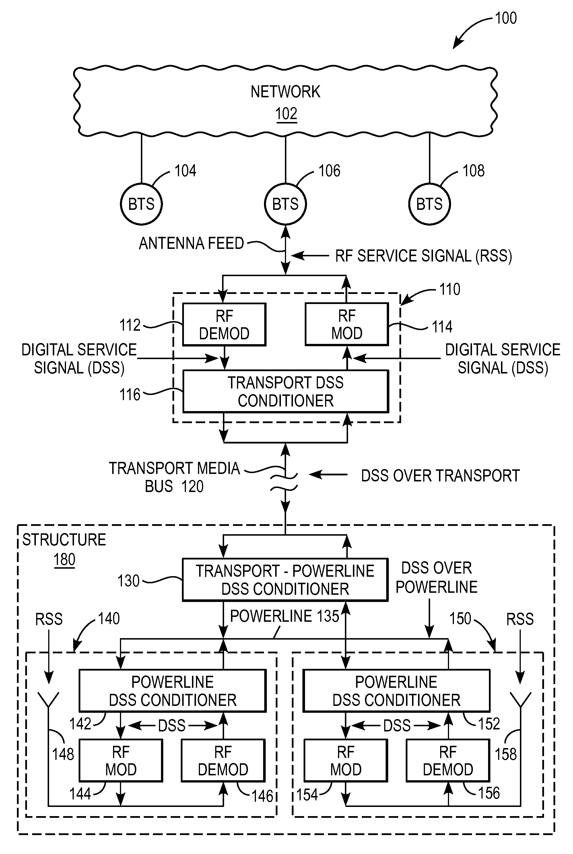
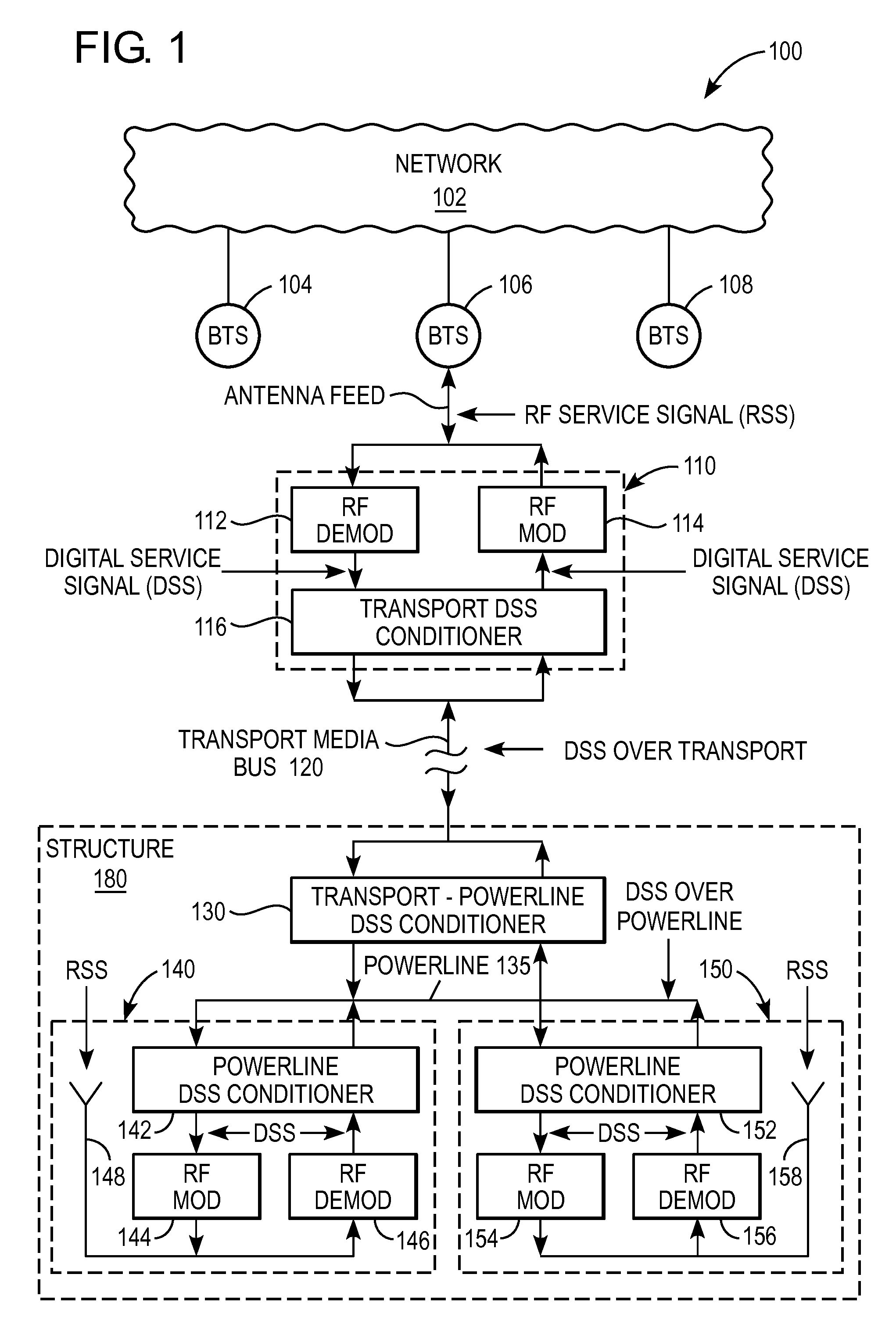
FIG. 1 illustrates a block diagram of an exemplary communication system 100 in accordance with an embodiment of the invention. The communication system 100 is particularly suited for improving the wireless coverage inside a structure 180, such as a building, dwelling, residence, tunnel, subway, or other structure defining an interior region for improved wireless coverage. The communication system 100 can be broken down into three subsystems, a network-side subsystem, a structure-side subsystem, and a communication medium connecting the network-side subsystem to the structure-side subsystem.
More specifically, on the network-side, the communication system 100 comprises a network 102, a plurality of base transceiver stations (BTS) 104, 106, and 108 coupled to the network 102, and a signal conditioner 110 connected to the BTS 106. It shall be understood that other similar signal conditioners may be connected to BTS 104 and 108, respectively. Also, one or more BTS may be connected to signal conditioner 110.
The network 102 includes a plurality of network devices configured to provide the specified wireless services for subscribers. For example, the specified wireless services may include interconnect (cellular) communication services, dispatch communication services, data communication services, and other wireless communication services. The network 102 may be based on any number of technologies and/or protocols. For example, the network 102 may be based on internet protocol (IP), Ethernet in accordance with the Institute of Electrical and Electronic Engineers (IEEE) 802.3 standards, Synchronous Optical NETwork (SONET), asynchronous transfer mode (ATM), frame relay, WiMAX or others including proprietary technologies and/or protocols.
The BTS 104, 106, and 108 serve as a signal interface between the wireless environment in which subscriber units reside, and the wired or wireless environment of the network 102. The BTS 104, 106, and 108 may generate and receive RF service signals (RSS) in accordance with any of a number of technologies and/or protocols, including Code Division Multiple Access (CDMA), Time Division Multiple Access (TDMA), Orthogonal Frequency Division Multiple Access (OFDMA), and others.
The signal conditioner 110 recovers the forward link digital service signal (DSS) from the forward link RF service signal (RSS) received from the antenna feed of the BTS 106 by demodulating the RSS, and also transmits the recovered forward link DSS to the structure 180 via a transport media bus 120. The signal conditioner 110 also modulates a radio frequency (RF) carrier with the reverse link DSS received from the structure 180 via the transport media bus 120 to produce an analog RF signal (i.e., the reverse link RSS) for transmission to the BTS 106 via its antenna feed.
The forward link DSS is the digital signal generated internally in the BTS 106 prior to it modulating an RF carrier for transmission. The forward link DSS includes the digital information sent via the access control channels, common channels, traffic channels, and/or other digital information sent to subscriber units. The reverse link DSS is the digital signal generated internally by a signal conditioner by demodulating an RSS which it receives over the air through an antenna. The reverse link DSS is comprised of a summation of one or more reverse link DSS generated internally by one or more subscriber units prior to each one modulating an RF carrier with its reverse link DSS for transmission via the wireless medium by radiating the RSS through a subscriber unit's antenna. The reverse link DSS includes the digital information sent via the access control channels, common channels, traffic channels, and/or other digital information sent toward a BTS.
In particular, the signal conditioner 110 comprises an RF demodulator 112, an RF modulator 114, and a transport DSS conditioner 116. The RF demodulator 112 demodulates the forward link RSS it receives from the BTS 106 via its antenna feed to produce the forward link DSS. In the forward link, the transport DSS conditioner 116 conditions the DSS it receives from the RF demodulator 112 for transmission via the transport media bus 120 (DSS over transport). In the reverse link, the transport DSS conditioner 116 extracts the DSS from the transport media bus 120. The RF modulator 114 modulates an RF carrier with the reverse link DSS it receives from the transport DSS conditioner 116 to generate the reverse link RSS and provides it to the BTS 106 via its antenna feed.
The transport media bus 120 may be any medium for transmitting the DSS between the signal conditioner 110 and the structure-side system. The transport media bus 120 may include wired physical medium, such as coaxial cable, optical fiber, twisted pair of copper wires, or electrical power lines. The transport media bus 120 may include any broadband technology or protocol, such as IEEE 1901, HomePlug, or other standard or proprietary Power Line Communication protocol, International Telecommunication Union-Telecommunications (ITU-T) recommendation G.993.2 Very high-bit-rate Digital Subscriber line, 2nd Generation (VDSL2), Ethernet in accordance with the Institute of Electrical and Electronic Engineers (IEEE) 802.3 standards, Synchronous Optical NETwork (SONET), and others. The transport media bus 120 may also include radio frequency (RF) over wireless medium, such as millimeter wave radio, Broadband Radio Spectrum, Free Space Optics, microwave radio, and others.
On the structure side, the communication system 100 comprises a transport-powerline DSS conditioner 130 connected to the transport media bus 120, and a plurality of distributed antenna modules 140 and 150 in communication with the transport-powerline DSS conditioner 130 via the electrical powerline 135 of the structure 180. Each distributed antenna module (140 and 150) includes a powerline DSS conditioner (142 and 152), an RF modulator (144 and 154), an RF demodulator (146 and 156), and an antenna (148 and 158). Although, in this example, two distributed antenna modules 140 and 150 are shown, it shall be understood that there may be any number of distributed antenna modules situated within the structure 180 to provide adequate wireless coverage.
Each distributed antenna module (140 and 150) may be configured as a small electrical appliance which serves as a wireless service signal antenna, with an optional repeater, and plugs into a standard wall outlet connected to the powerline 135 of the structure 180. As discussed in more detail below, the small electrical appliance contains a signal conditioner, which demodulates a reverse link RSS received from its antenna to generate a reverse link DSS and transmits it toward the BTS, and which modulates an RF carrier with a forward link DSS received over the powerline 135 of the structure 180 to create a forward link RSS for transmission over its antenna.
In the forward link, the transport-powerline DSS conditioner 130 extracts the DSS from the transport media bus 120, and conditions the digital service signal (DSS) for transmission via the powerline 135 of the structure 180. In the reverse link, the transport-powerline DSS conditioner 130 extracts the digital service signal (DSS) from the powerline 135, and conditions the digital service signal (DSS) for transmission via the transport media bus 120. The digital service signal (DSS) may be placed on the powerline 135 using many different techniques and/or protocols, such as Broadband over Powerline, HomePlug, or IEEE 1901.
In the forward link, the powerline DSS conditioner (142 and 152) of the distributed antenna modules (140 and 150) extracts the digital service signal (DSS) from the powerline 135. The RF modulator (144 and 154) of the distributed antenna modules (140 and 150) modulates an RF carrier with the DSS received from the powerline DSS conditioner (142 and 152) to form the RSS, and sends it to the antenna (148 and 158) for transmission via the wireless medium within the structure 180. In the reverse link, the RF demodulator (146 and 156) receives the reverse link RSS from subscriber units via the antenna (148 and 158) and demodulates the RSS to generate the DSS. The powerline DSS conditioner (142 and 152) conditions the DSS it receives from the RF demodulator (146 and 156) for transmission via the powerline 135.
In summary, in the forward link, the RSS generated by the BTS 106 by modulating an RF carrier with the original DSS, is sent to subscriber units residing within the structure 180 by way of the signal conditioner 110, transport media bus 120, transport-powerline DSS conditioner 130, powerline 135, and the distributed antenna modules 140 and 150. Along the way, the RSS is demodulated to recover the DSS and conditioned for transmission via the transport media bus 120 by the signal conditioner 110; then the DSS is conditioned for transmission via the powerline 135 by the transport-powerline DSS conditioner 130; and then an RF carrier is modulated by the DSS to generate an RSS, which is radiated as an RSS by the distributed antenna modules 140 and 150 for reception by the subscriber units within the structure 180.
In the reverse link, the RSS generated by subscriber units within the structure 180 is sent to the BTS 106 by way of the corresponding distributed antenna module (140 and 150), the powerline 135, the transport-powerline DSS conditioner 130, transport media bus 120, and signal conditioner 110. Along the way, the RSS is demodulated to generate the DSS for transmission via the powerline 135 by the corresponding distributed antenna module (140 and 150); then the DSS is conditioned for transmission via the transport media bus 120 by the transport-powerline DSS conditioner 130; and then an RF carrier is modulated with the DSS by the signal conditioner 110 to generate the RSS for transmission to the BTS 106 over an antenna feed.
The communication system 100 has several advantages over prior attempts of providing improved in-building wireless coverage. First, because the transmission via the powerline 135 of the structure 180 is the recovered DSS, the bandwidth requirement is much less than that for RF analog transmission, or alternatively, much less than that for a digitized RF signal that is created by sampling the RSS, at a rate at least twice that of the bandwidth, according to the Nyquist theorem, to create a digitized representation of the analog RF signal. Consequently, the existing low voltage powerline of the structure 180 can be used. Second, because the DSS is transmitted using the existing powerline 135 of the structure 180, there is no need to incur costs associated with obtaining a dedicated physical medium and the labor to route it within the structure 180. Third, because the transmission via the powerline is in digital format, it is less susceptible to signal degradation due to noise and/or inter-modulation products than an analog RSS. The following exemplary embodiments provide several variations of communication system 100.
FIG. 2 illustrates a block diagram of another exemplary communication system 200 in accordance with another embodiment of the invention. The communication system 200 is a variation of communication system 100. Elements common to both systems 100 and 200 have the same reference numbers, except the most significant digit is a “2” for system 200 and a “1” for system 100. The detailed discussion of these common elements has been provided above with reference to communication system 100.
In communication system 200, the RSS is transmitted to and received from the structure over the wireless medium in accordance with the normal operation of a typical BTS; the demodulation of the RSS to recover the DSS, and vice versa, is performed by a modified signal conditioner 211 residing in the structure 280; and the modified signal conditioner 211 conditions the DSS for transmission via the powerline 235 of the structure 280 (instead of the transport media bus), and extracts the DSS directly from the powerline 235 (instead of the transport media bus). Accordingly, in communication system 200, there is no need for a transport media bus.
In the forward link, the RSS generated by the BTS 106 is sent over the wireless medium, and picked up by an antenna 209 at the structure 280. The modified signal conditioner 211 demodulates the received RSS to recover the DSS for transmission via the powerline 235. The distributed antenna modules 240 and 250 modulate an RF carrier with the DSS received via the powerline 235 to generate the RSS for transmission to the subscriber units within the structure 280.
In the reverse link, the distributed antenna module (240 and/or 250) receives the RSS generated by one or more subscriber units within the structure 280, and demodulates it to generate the DSS for transmission via the powerline 235. The modified signal conditioner 211 receives the DSS from the powerline 235, and modulates an RF carrier to generate the RSS for wireless transmission to the BTS 206 by way of the antenna 209.
FIG. 3 illustrates a block diagram of another exemplary communication system 300 in accordance with another embodiment of the invention. The communication system 300 is a variation of communication system 200. Elements common to both systems 300 and 200 have the same reference numbers, except the most significant digit is a “3” for system 300, and a “2” for system 200. The detailed discussion of these common elements has been provided above.
In communication system 300, the BTS 306 is located at the structure 380. Accordingly, the signal conditioner 311 receives the forward link RSS via the antenna feed of the BTS 306 instead of over the air as in system 200. Everything else is substantially the same as in communication system 200.
Accordingly, in the forward link, the RSS generated by the BTS 306 is sent to the signal conditioner 311 via the antenna feed of the BTS 306. The signal conditioner 311 demodulates the received RSS to recover the DSS for transmission via the powerline 335. The distributed antenna modules 340 and 350 modulate an RF carrier with the DSS received via the powerline 335 to generate the RSS for transmission to the subscriber units within the structure 380.
In the reverse link, the distributed antenna module (340 and/or 350) receives the RSS generated by one or more subscriber units within the structure 380, demodulates it to generate the DSS, and conditions the DSS for transmission via the powerline 335. The signal conditioner 311 receives the DSS from the powerline 335, and modulates an RF carrier with the DSS to generate the RSS for transmission to the BTS 306 by way of its antenna feed.
FIG. 4 illustrates a block diagram of another exemplary communication system 400 in accordance with another embodiment of the invention. The communication system 400 is a variation of communication system 100. Elements common to both systems 400 and 100 have the same reference numbers, except the most significant digit is a “4” for system 400, and a “1” for system 100. The detailed discussion of these common elements has been provided above.
In communication system 400, the BTS 407 is modified to directly produce and receive the DSS, e.g., an open BTS designed to communicate with a remote Radio Frequency head. Due to this, there is no need for the RF modulator and demodulator of the signal conditioner 110 of communication system 100. Instead, the communication system 400 incorporates the transport DSS conditioner 416 to condition the DSS it receives directly from the BTS 407 for transmission via the transport media bus 420 in the forward link, and extracts the DSS from the transport media bus 420 and sends it directly to the BTS 407 in the reverse link. Everything else is substantially the same as in communication system 100.
Accordingly, in the forward link, the transport DSS conditioner 416 conditions the DSS it has received directly from the BTS 407 for transmission via the transport media bus 420. The powerline-transport DSS conditioner 430 conditions the DSS it has received by way of the transport media bus 420 for transmission via the structure powerline 435. The distributed antenna modules 440 and 450 each modulates an RF carrier with the DSS received via the powerline 435 to generate the RSS for transmission to the subscriber units within the structure 480.
In the reverse link, the distributed antenna module (440 and/or 450) receives the RSS generated by one or more subscriber units within the structure 480, and demodulates it to generate the DSS for transmission via the powerline 435. The transport-powerline DSS conditioner 430 conditions the DSS it receives via the powerline 435 for transmission via the transport media bus 420. The transport DSS conditioner 416 extracts the DSS from the transport media bus 420, and provides it directly to the BTS 407.
The distributed antenna modules and the various conditioners, may have a relatively small form factor, comparable to a night light or plug-in air freshener. They may be configured to plug directly into a standard electrical outlet, conforming to a standard or protocol for PowerLine Communications, such as HomePlug or IEEE 1901 or others. The distributed antenna module may contain a signal conditioner within the same small electrical appliance. In other words, the distributed antenna modules may be designed to blend into a household.
While the invention has been described in connection with various embodiments, it will be understood that the invention is capable of further modifications. This application is intended to cover any variations, uses or adaptation of the invention following, in general, the principles of the invention, and including such departures from the present disclosure as come within the known and customary practice within the art to which the invention pertains.

PUM

no PUM

Description & Claims & Application Information

We can also present the details of the Description, Claims and Application information to help users get a comprehensive understanding of the technical details of the patent, such as background art, summary of invention, brief description of drawings, description of embodiments, and other original content. On the other hand, users can also determine the specific scope of protection of the technology through the list of claims; as well as understand the changes in the life cycle of the technology with the presentation of the patent timeline. Login to view more.

Similar technology patents

Bandwidth modulation system and method

ActiveUS9035992B1reduce bandwidth requirement
Owner:GOOGLE LLC

Low-power and high-performance video coding method for performing motion estimation

ActiveUS20100195734A1reduce bandwidth requirement
Owner:ACER INC

Storage devices with soft processing

ActiveUS9036420B2reduce bandwidth requirementlower power consumption
Owner:ANALOG DEVICES INC

Real-time dynamic hyperlinking system and method

InactiveUS20160080451A1reduce bandwidth requirement
Owner:GAZOO

Systems, methods and computer program products for collaborative agent control

ActiveUS11334069B1reduce bandwidth requirementimprove quality
Owner:NAT TECH & ENG SOLUTIONS OF SANDIA LLC

Classification and recommendation of technical efficacy words

  • reduce bandwidth requirement
  • low cost

Mobile terminal with a text-to-speech converter

InactiveUS6931255B2reduce bandwidth requirement
Owner:TELEFON AB LM ERICSSON (PUBL)

Reuseable configuration data

ActiveUS20060095720A1reduce bandwidth requirementreadily retrieve
Owner:ARM LTD +1

Methods and computer systems for document encryption

ActiveUS20050235165A1reduce bandwidth requirement
Owner:SAP AG

Hash Level Load Balancing For Deduplication Of Network Packets

ActiveUS20160149820A1reduce bandwidth requirementincrease flexibility
Owner:KEYSIGHT TECH SINGAPORE (SALES) PTE LTD

Dynamic data filtering

InactiveUS20090059941A1reduce bandwidth requirement
Owner:CHICAGO MERCANTILE EXCHANGE

Plastic waveguide-fed horn antenna

InactiveUS20100214185A1low cost
Owner:RGT UNIV OF CALIFORNIA

System and method for determination of position

InactiveUS20090149202A1low costreduce requirement
Owner:STEELE CHRISTIAN

Adaptive antenna optimization network

InactiveUS6961368B2low costminimal space
Owner:ERICSSON INC

Antenna device and method for attaching the same

ActiveUS20150138022A1low costimproved strength characteristic
Owner:NEC CORP
Why Eureka
Try Eureka