Heat exchanger with fluid expansion in header

a heat exchanger and header technology, applied in indirect heat exchangers, lighting and heating apparatuses, refrigeration components, etc., can solve problems such as reducing heat exchanger efficiency, affecting heat exchanger efficiency, and two-phase maldistribution, and achieve the effect of reducing maldistribution

Inactive Publication Date: 2011-04-26
CARRIER CORP
View PDF51 Cites 12 Cited by
  • Summary
  • Abstract
  • Description
  • Claims
  • Application Information

AI Technical Summary

Benefits of technology

[0012]It is a general object of the invention to reduce maldistribution of refrigerant flow in a refrigerant vapor compression system heat exchanger having a plurality of multi-channel tubes extending between a first header and a second header.

Problems solved by technology

Non-uniform distribution, also referred to as maldistribution, of two-phase refrigerant flow is a common problem in parallel tube heat exchangers which adversely impacts heat exchanger efficiency.
Two-phase maldistribution problems are often caused by the difference in density of the vapor phase refrigerant and the liquid phase refrigerant present in the inlet header due to the expansion of the refrigerant as it traversed the upstream expansion device.
Obtaining uniform refrigerant flow distribution amongst the relatively large number of small flow area refrigerant flow paths is even more difficult than it is in conventional round tube heat exchangers and can significantly reduce heat exchanger efficiency as well as cause serious reliability problems due to compressor flooding.

Method used


Image

  • Heat exchanger with fluid expansion in header
  • Heat exchanger with fluid expansion in header
  • Heat exchanger with fluid expansion in header

Examples


Embodiment Construction

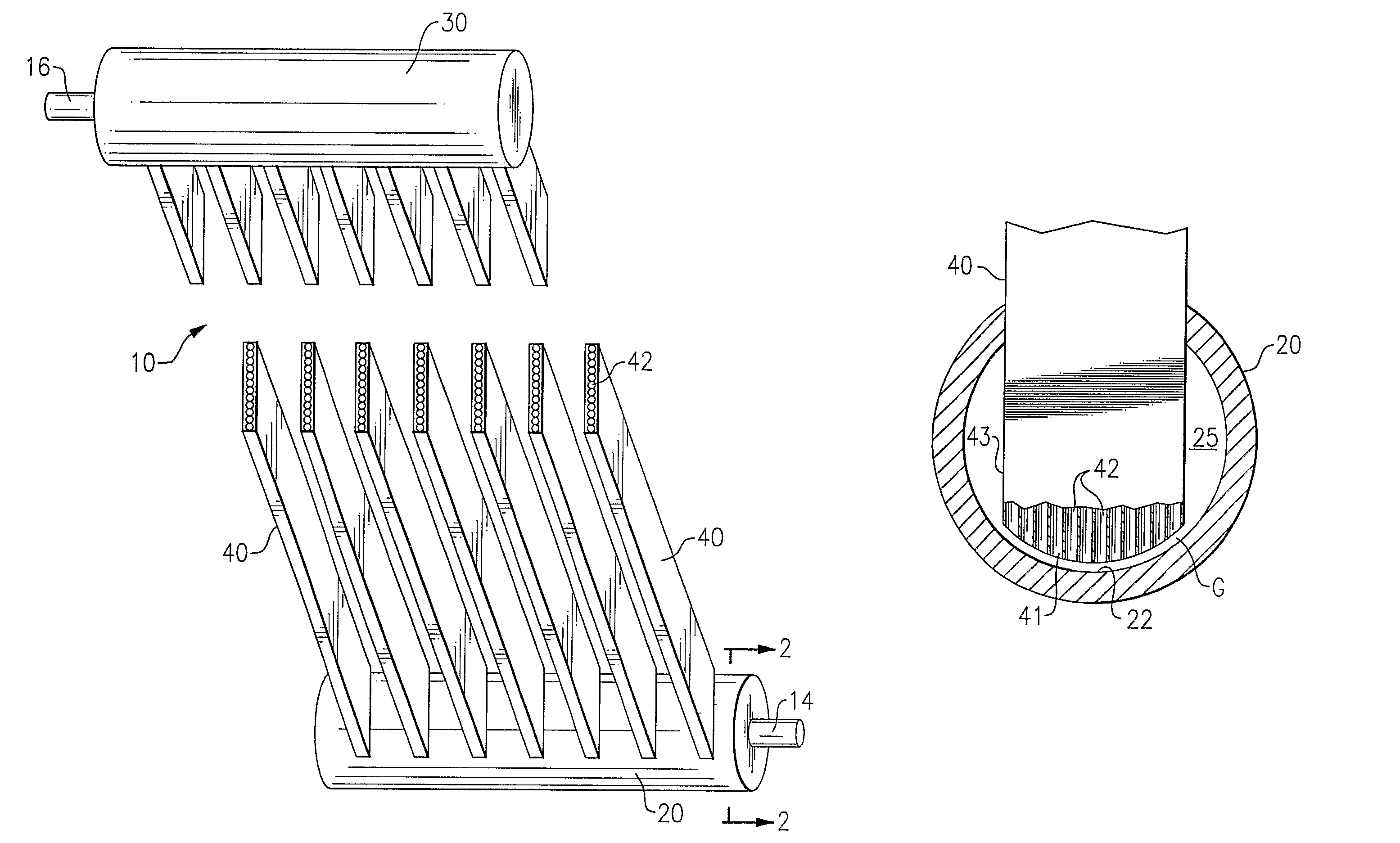
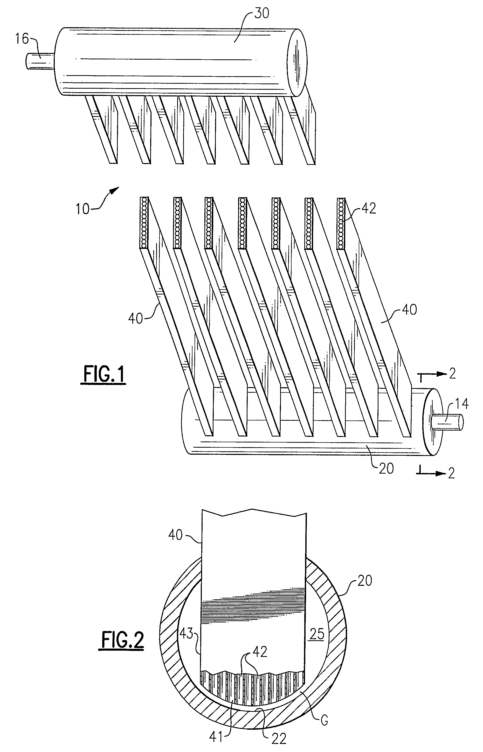
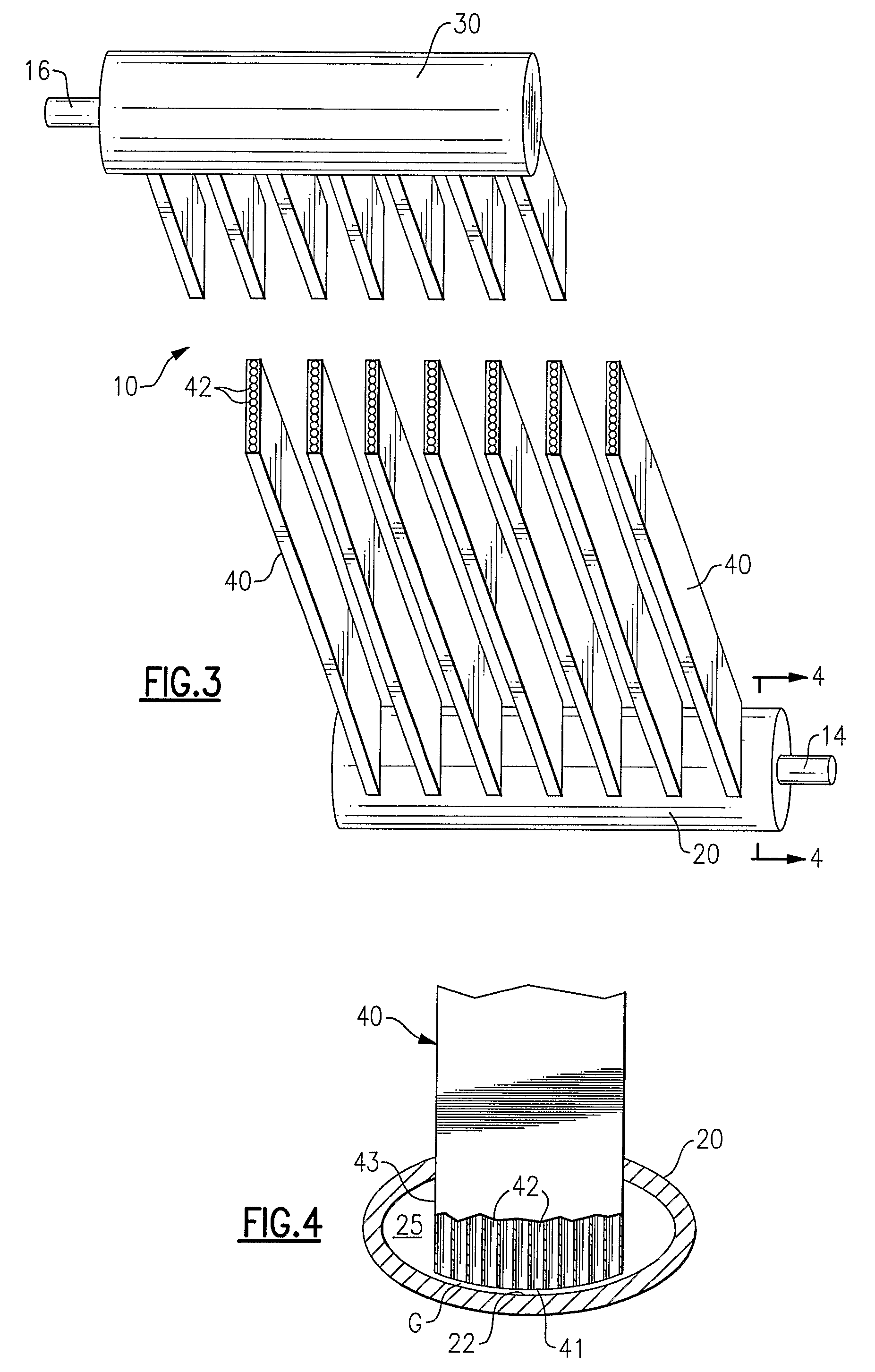
[0032]The parallel tube heat exchanger 10 of the invention will be described herein in general with reference to the various illustrative single pass embodiments of a multi-channel tube heat exchanger as depicted in FIGS. 1-8. The heat exchanger 10 includes an inlet header 20, an outlet header 30, and a plurality of multi-channel heat exchange tubes 40 extending longitudinally between the inlet header 20 and the outlet header 30 thereby providing a plurality of refrigerant flow paths between the inlet header 20 and the outlet header 30. Each heat exchange tube 40 has an inlet 43 at one end in refrigerant flow communication to the inlet header 20 and an outlet at its other end in refrigerant flow communication to the outlet header 30.

[0033]In the illustrative embodiments of the heat exchanger 10 depicted in FIGS. 1, 3, 5 and 7, the heat exchange tubes 40 are shown arranged in parallel relationship extending generally vertically between a generally horizontally extending inlet header ...


PUM


Abstract

A heat exchanger includes a first header and a second header and a plurality of heat exchange tubes extending therebetween. Each heat exchange tube has an inlet end opening to one of the headers and an outlet opening to the other header. Each heat exchange tube has a plurality of channels extending longitudinally in parallel relationship from its inlet end to its outlet end, each channel defining a discrete refrigerant flow path. The inlet end of each of the plurality of heat exchange tubes is positioned with the inlet opening to the channels disposed in spaced relationship with and facing an opposite inside surface of the header thereby defining a relatively narrow gap between the inlet opening to the channels and the facing opposite inside surface of the header. The gap may function either as a primary expansion device or as a secondary expansion device.

Description

CROSS-REFERENCE TO RELATED APPLICATION[0001]Reference is made to and this application claims priority from and the benefit of U.S. Provisional Application Ser. No. 60 / 649,422, filed Feb. 2, 2005, and entitled MINI-CHANNEL HEAT EXCHANGER WITH FLUID EXPANSION IN A GAP BETWEEN THE TUBE AND THE HEADER, which application is incorporated herein in its entirety by referenceFIELD OF THE INVENTION[0002]This invention relates generally to refrigerant vapor compression system heat exchangers having a plurality of parallel tubes extending between a first header and a second header and, more particularly, to providing expansion of refrigerant within the inlet header for improving distribution of two-phase refrigerant flow through the parallel tubes of the heat exchanger.BACKGROUND OF THE INVENTION[0003]Refrigerant vapor compression systems are well known in the art. Air conditioners and heat pumps employing refrigerant vapor compression cycles are commonly used for cooling or cooling / heating air...

Claims


Application Information

Patent Timeline
Patent Type & Authority Patents(United States)
IPC IPC(8): F28F9/02
CPCF25B39/028F28D1/05391F28F9/026F25B41/30
Inventor GORBOUNOV, MIKHAIL B.VERMA, PARMESHTARAS, MICHAEL F.CHOPKO, ROBERT A.KIRKWOOD, ALLEN C.
Owner CARRIER CORP
Why Eureka
Try Eureka