Lane marker recognition apparatus

a recognition apparatus and lane marker technology, applied in the field of vehicle lane marker recognition apparatus, can solve problems such as misrecognition of lane markers, and achieve the effect of robustly recognizing lane markers

Active Publication Date: 2011-04-26
DENSO CORP
View PDF14 Cites 20 Cited by
  • Summary
  • Abstract
  • Description
  • Claims
  • Application Information

AI Technical Summary

Benefits of technology

[0006]It is an object of the present invention to provide a vehicular lane marker recognition apparatus for robustly recognizing a lane marker without limitation to a specific road condition.

Problems solved by technology

When a road curves with a large amount of curvature, data on reflection from a lane marker cannot be accurately extracted, resulting in mis-recognition of a lane marker.

Method used


Image

  • Lane marker recognition apparatus
  • Lane marker recognition apparatus
  • Lane marker recognition apparatus

Examples


Embodiment Construction

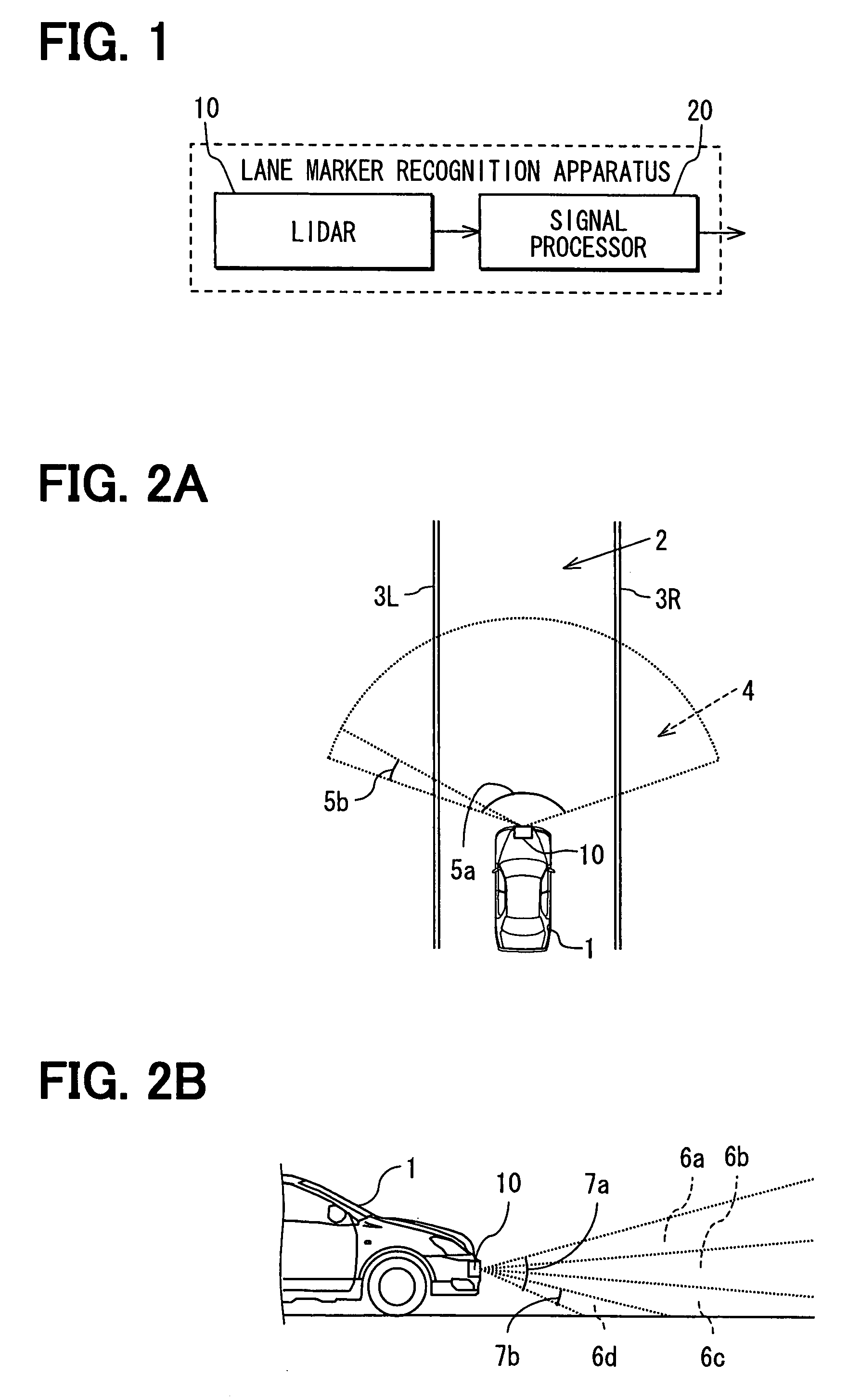
[0022]A vehicular lane marker recognition apparatus according to an embodiment of the present invention will be explained below. The apparatus performs recognitions for lane markers on roads periodically (i.e., with repeated cycles from a past cycle (including a previous cycle) to a present cycle, further to a future cycle (including a next cycle). The apparatus is provided in a subject vehicle and includes a lidar instrument 10 (i.e., a laser radar instrument) and a signal processor 20, as shown in FIG. 1.

[0023]The lidar instrument 10 is a known in-vehicle laser radar sensor. It scans (i.e., radiates laser beams to) surfaces of a road ahead of (i.e., frontward of) the subject vehicle in a range having a predetermined angle, and receives the reflection. Here, the lidar instrument 10 may scan surfaces rearward of the subject vehicle. The lidar instrument 10 measures a distance to a reflection object (i.e., an on-road characteristic object) on the surface of the road within the radiat...


PUM


Abstract

Data on a lane marker are extracted based on a centerline position, centerline shape, and width of a lane, which are projected for the present cycle. Data on a lane centerline are generated by adjusting x-axis components of the extracted data. A centerline position and centerline shape is calculated with the Hough's transformation using the generated data on the lane centerline. A frequency distribution is calculated for opposing positions with respect to the lane centerline. A lane width of the road is calculated by calculating an auto-correlation function with respect to the frequency distribution. A centerline position, centerline shape, and lane width at the present cycle and subsequent cycles are estimated / projected with the Kalman filter.

Description

CROSS REFERENCE TO RELATED APPLICATION[0001]This application is based on and incorporates herein by reference Japanese Patent Application No. 2006-143204 filed on May 23, 2006.FIELD OF THE INVENTION[0002]The present invention relates to a vehicular lane marker recognition apparatus for recognizing a lane marker on a road.BACKGROUND OF THE INVENTION[0003]Patent document 1 discloses a calculation to specify a lane marker based on data on reflection from a road surface using a lidar (i.e., laser radar) instrument mounted in a vehicle. Here, data on a plane parallel with a road surface are subjected to a frequency distribution in a vehicle's axle directional component. Data included in a certain segment where the frequency reaches the local maximum value is extracted as data on reflection from a lane marker. The extracted data is then subjected to a method of least square or Hough's transformation to thereby compute a parameter to specify the lane marker.[0004]Patent document 1: JP-A-20...

Claims


Application Information

Patent Timeline
Patent Type & Authority Patents(United States)
IPC IPC(8): G06K9/00G06V10/44
CPCG01S17/936G06K9/4604G01S17/931G06V10/44
Inventor OGAWA, TAKASHI
Owner DENSO CORP
Why Eureka
Try Eureka