Developing device frame unit, developing device, process cartridge, and manufacturing method of the developing device frame unit

a technology of developing device and frame unit, which is applied in the direction of electrographic process apparatus, instruments, optics, etc., can solve the problems of increasing assembly time and increasing cos

Active Publication Date: 2011-04-26
CANON KK
View PDF73 Cites 101 Cited by
  • Summary
  • Abstract
  • Description
  • Claims
  • Application Information

AI Technical Summary

Benefits of technology

[0022]Another object of the present invention is to provide a developing device frame unit, a developing device, a process cartridge, and a manufacturing method of the developing device frame unit, in which the blade seal member is formed with no gap with one end seal member and with no gap with the other end seal member to realize a simple seal constitution and a reduction in the number of assembly steps, thus resulting in a reduction of manufacturing costs.
[0023]As further object of the present invention, there is provided a developing device frame unit, a developing device, a process cartridge, and a manufacturing method of the developing device frame unit, in which the assembling property of the blade is improved by being directly formed on a developing device frame.
[0024]According to an aspect of the present invention, there is provided a developing device frame unit for supporting a regulating member for regulating the layer thickness of a developer on a developer carrying member. The developing device frame unit comprises a developing device frame having a seal forming portion, a one end sealing member which is provided at one longitudinal end of the developing device frame and which is contactable to a surface of the developer carrying member to prevent the developer from leaking in an axial direction of the developer carrying member when the developer carrying member is mounted to the developing device frame unit, an other end sealing member which is provided at the other longitudinal end of the developing device frame and which is contactable to the surface of the developer carrying member to prevent the developer from leaking in an axial direction of the developer carrying member when the developer carrying member is mounted to the developing device frame unit, and a blade sealing member for providing a seal between the regulating member and the developing device frame to prevent the developer from leaking when the regulating member is mounted. The blade sealing member is an elastomer resin material which is injection-molded with a metal mold and which is provided in the seal forming portion where the one end sealing member and the other end sealing member are provided. The blade sealing member connects the one end sealing member and the other end sealing member with each other. The developing device frame unit also includes a protrusion provided by a squeezed-out portion of the elastomer resin material. The squeezed-out portion is provided by injecting, into a space defined by the metal mold, the seal forming portion, the one end sealing member and the other end sealing member, a volume of the elastomer resin material that is larger than the volume of the space.
[0027]According to a further aspect of the present invention, there is provided a manufacturing method for a developing device frame unit for supporting a regulating member for regulating the layer thickness of a developer on a developer carrying member. The method comprises a step of mounting a first end sealing member which is provided at one longitudinal end of the developing device frame and which is contactable to a surface of the developer carrying member to prevent the developer from leaking in an axial direction of the developer carrying member when the developer carrying member is mounted to the developing device frame unit, a step of mounting a second end sealing member which is provided at the other longitudinal end of the developing device frame and which is contactable to the surface of the developer carrying member to prevent the developer from leaking in an axial direction of the developer carrying member when the developer carrying member is mounted to the developing device frame unit, and a sealing member molding step of molding a blade sealing member for providing a seal between the regulating member and the developing device frame to prevent the developer from leaking when the regulating member is mounted to the developing device frame unit. The blade sealing member is an elastomer resin material which is injection-molded with a metal mold and which is provided in the seal forming portion where the first end sealing member and the second end sealing member are provided. The blade sealing member connects the first end sealing member and the second end sealing member with each other. The molding step includes providing a protrusion provided by a squeezed-out portion of the elastomer resin material. The squeezed-out portion is provided by injecting, into a space defined by the metal mold, the seal forming portion, the first end sealing member and the second end sealing member, a volume of the elastomer resin material larger than a volume of the space.

Problems solved by technology

However, the above-described conventional seal constitutions have the following problem.
However, in this method, an additional injection step of injecting the bulking material 92 was required to result in an increase in cost due to an increase in assembly time.

Method used


Image

  • Developing device frame unit, developing device, process cartridge, and manufacturing method of the developing device frame unit
  • Developing device frame unit, developing device, process cartridge, and manufacturing method of the developing device frame unit
  • Developing device frame unit, developing device, process cartridge, and manufacturing method of the developing device frame unit

Examples


embodiment 1

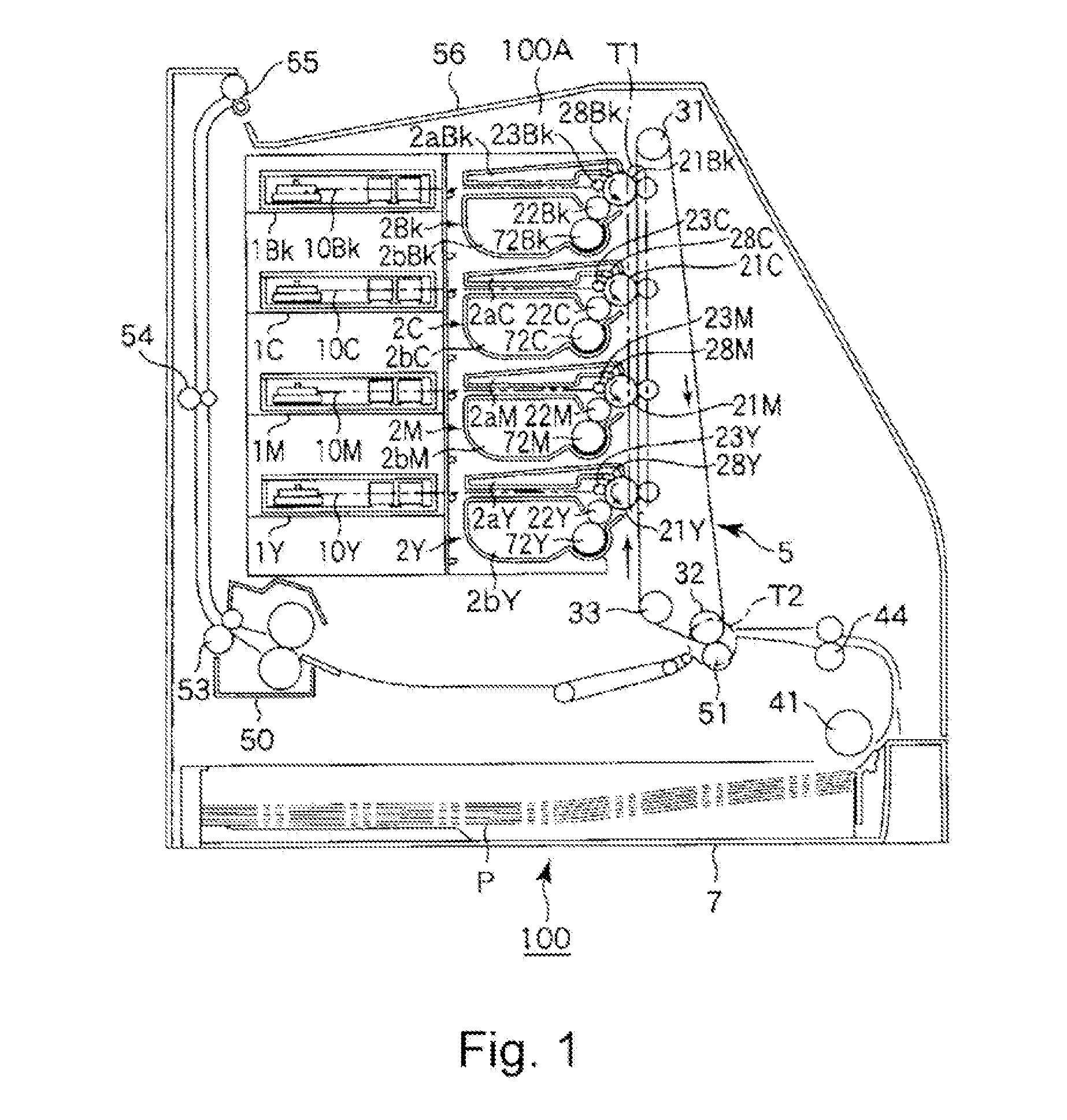
[0052]FIG. 1 shows a general arrangement of a color laser beam printer, using an electrophotographic process, as an embodiment of an image forming apparatus to which the present invention is to be applied.

(General Arrangement)

[0053]In this embodiment, the image forming apparatus 100 includes four independent process cartridges 2 (2Y, 2M, 2C, 2Bk) which are detachably mountable to an apparatus main assembly 100A and are arranged vertically. In this embodiment, the process cartridges 2 (2Y, 2M, 2C and 2Bk) include image forming means for yellow (Y) toner, magenta (M) toner, cyan (C) toner, and black (Bk) toner, respectively. In the following description, a “longitudinal direction” of the process cartridge means a direction substantially perpendicular to a direction in which the process cartridge is mounted into the main assembly 100A of the image forming apparatus 100 (i.e., a rotational axis direction of a photosensitive drum). Further, a “left (side)” and a “right (side)” are those ...

embodiment 2

[0103]FIGS. 16(a) and 16(b) are schematic front views showing positions of the buffer portions in Embodiment 2 as another embodiment of the present invention. In Embodiment 1, the communication ports 101a and 102a are provided at the positions on the flow path of the elastomer resin material from the injection ports to the end seal members at the seal forming portion and are located in the neighborhood of the end seal members 95a and 95b.

[0104]In Embodiment 2, a buffer portion 103 enclosed by dotted lines as shown in FIG. 16(a) is provided. The buffer portion 103 also falls within the buffer portion described above in the present invention, which is disposed between the end seal members 95a and 95b and in the neighborhood of the end seal members 95a and 95b.

[0105]By this constitution, the elastomer resin material closely contacts the end seal members 95a and 95b with reliability and thereafter flows into the buffer portion 103. As a result, an effect similar to that in Embodiment ...

embodiment 3

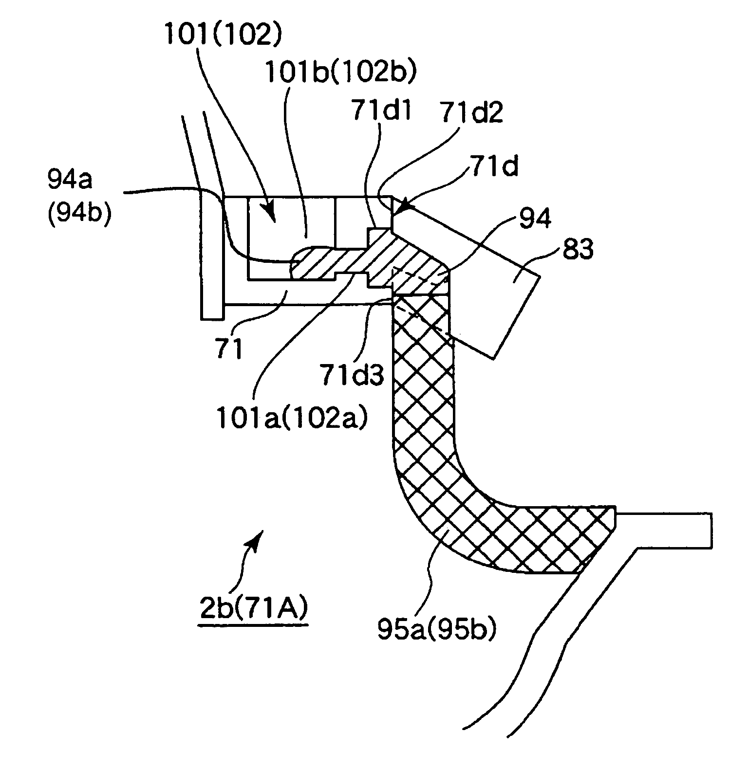
[0107]FIG. 21 is a schematic sectional view showing a buffer portion of the developing device frame unit 71A in Embodiment 3, FIG. 22 is a schematic front view showing a longitudinal end portion of the developing device frame unit 71A in a state in which an under blade seal 94 in Embodiment 3 is molded.

[0108]In Embodiment 1, the excessive portion 94a (94b) of the elastomer resin material is caused to flow into the resin material reservoir portion 101b (102b) of the buffer portion 101 (102).

[0109]In this embodiment, the resin material reservoir portion 101b (102b) is not provided for the excessive portion (protrusion) 94a (94b) of the elastomer resin material but a flow path 83a is provided to the mold 83 as shown in FIG. 21, so that the excessive portion of the elastomer resin material is caused to flow through the flow path 83a. The flow path 83a is provided at a position, as shown in FIG. 22, in which the excessive portion 94a (94b) of the elastomer resin material is caused to flo...


PUM


Abstract

A developing device frame unit supporting a regulating member regulating the layer thickness of developer on a developer carrier. The unit includes a frame having a seal forming portion, first and second, first and second end seals contactable to the carrier surface to prevent carrier-axial-direction leaking of the developer, and a blade sealer sealing between the regulating member and the frame to prevent developer leaking when the regulating member is mounted. The blade sealer is an elastomer resin material which is injection-molded with a metal mold and in the seal forming portion where the end seals are provided. The blade sealer connects the end seals with each other, and a protrusion provided by a squeezed-out portion of the resin material is provided by injecting, into a space defined by the metal mold, the seal forming portion, and the end seal seals, a resin material volume larger than a volume of the space.

Description

FIELD OF THE INVENTION AND RELATED ART[0001]The present invention relates to an electrophotographic image forming apparatus for forming an image on a recording medium in general. Particularly, the present invention relates to a developing device for developing an electrostatic latent image formed on an image bearing member in the electrophotographic image forming apparatus and a process cartridge detachably mountable to the electrophotographic image forming apparatus. Further, the present invention relates to a developing device frame unit having a regulating member for regulating the layer thickness of developer on a developer carrying member for developing the electrostatic latent image on the image bearing member and a manufacturing method of the developing device frame unit.[0002]The process cartridge is prepared by integrally supporting at least a developing means and an electrophotographic photosensitive drum and is detachably mountable to a main assembly of the electrophotogr...

Claims


Application Information

Patent Timeline
Patent Type & Authority Patents(United States)
IPC IPC(8): G03G15/08
CPCG03G15/0812G03G15/0898G03G15/08
Inventor HOSHI, NOBUHARUSUZUKI, AKIRAHAYASHIDA, MAKOTOKANNO, KAZUHIKOHORIKAWA, TADASHI
Owner CANON KK
Why Eureka
Try Eureka