Stirring apparatus

a technology of stirring apparatus and stirring chamber, which is applied in the direction of machines/engines, transportation and packaging, liquid fuel engines, etc., can solve the problems of increased manufacturing costs, difficult washing, and inability to improve stirring characteristics, so as to achieve appropriate stirring characteristics, increase the opening ratio, and satisfy the vertical circulation flow

Active Publication Date: 2011-05-03
SUMITOMO HEAVY IND PROCESS EQUIP CO LTD
View PDF44 Cites 6 Cited by
  • Summary
  • Abstract
  • Description
  • Claims
  • Application Information

AI Technical Summary

Benefits of technology

[0010]The stirring apparatus of the present invention is capable of creating a satisfactory vertical circulation flow throughout the inside of the tank and exhibiting appropriate stirring characteristics by increasing the opening ratio in the upper half of the stirring impeller, decreasing the opening ratio in the lower half, and optimizing these opening ratios.

Problems solved by technology

However, the small-sized blades hardly create a satisfactory vertical circulation flow throughout the inside of the tank, as illustrated in FIG. 14, and thereby creating plural isolated zones in the vertical direction, so that the stirring characteristics cannot be improved as expected.
In addition, these impellers tend to have complicated shapes, which causes increase in manufacturing costs and makes them difficult to wash.

Method used


Image

  • Stirring apparatus
  • Stirring apparatus
  • Stirring apparatus

Examples


Embodiment Construction

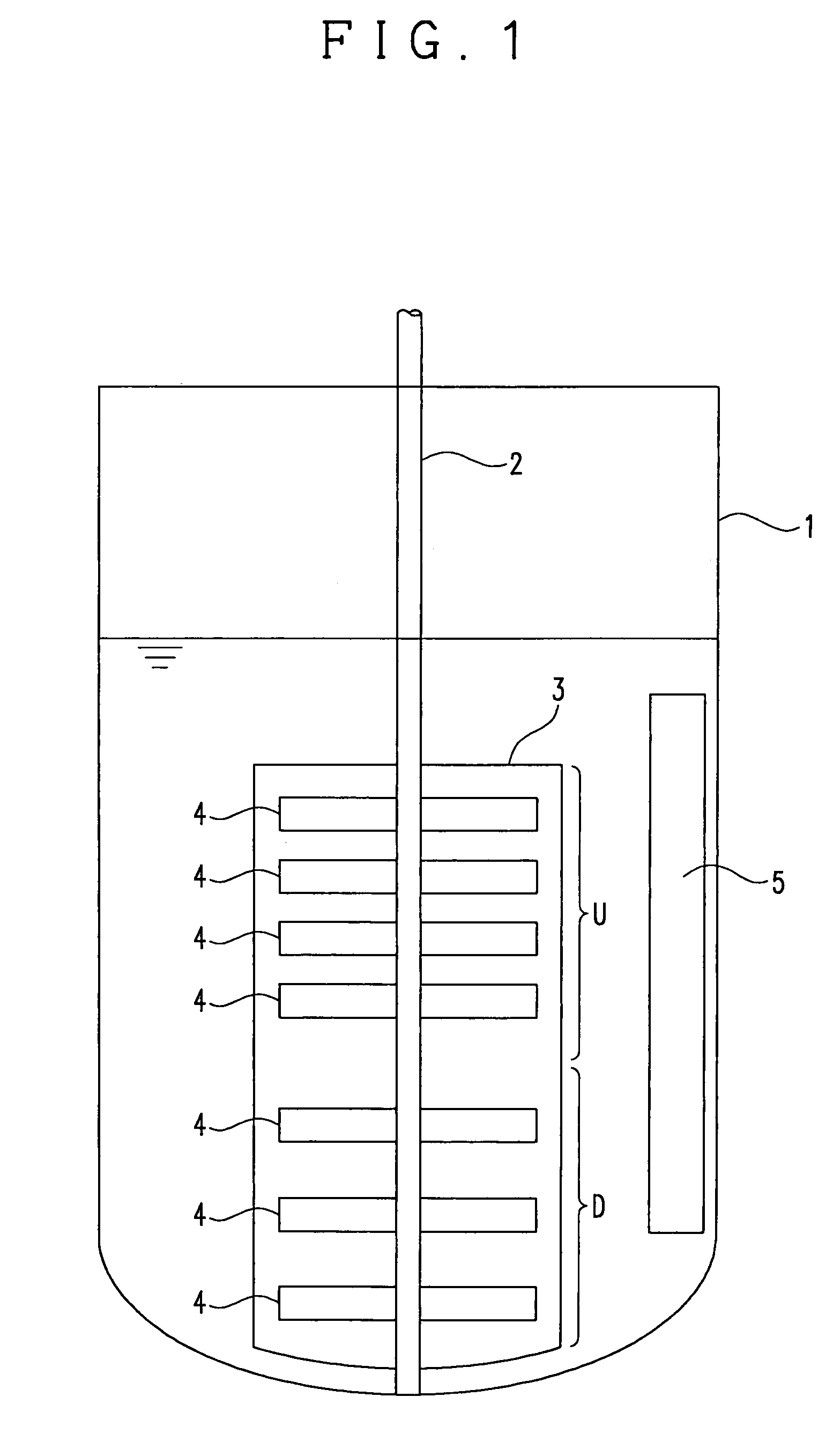
[0027]Now, the description will be made for a stirring apparatus of an embodiment of the present invention with reference to FIG. 1.

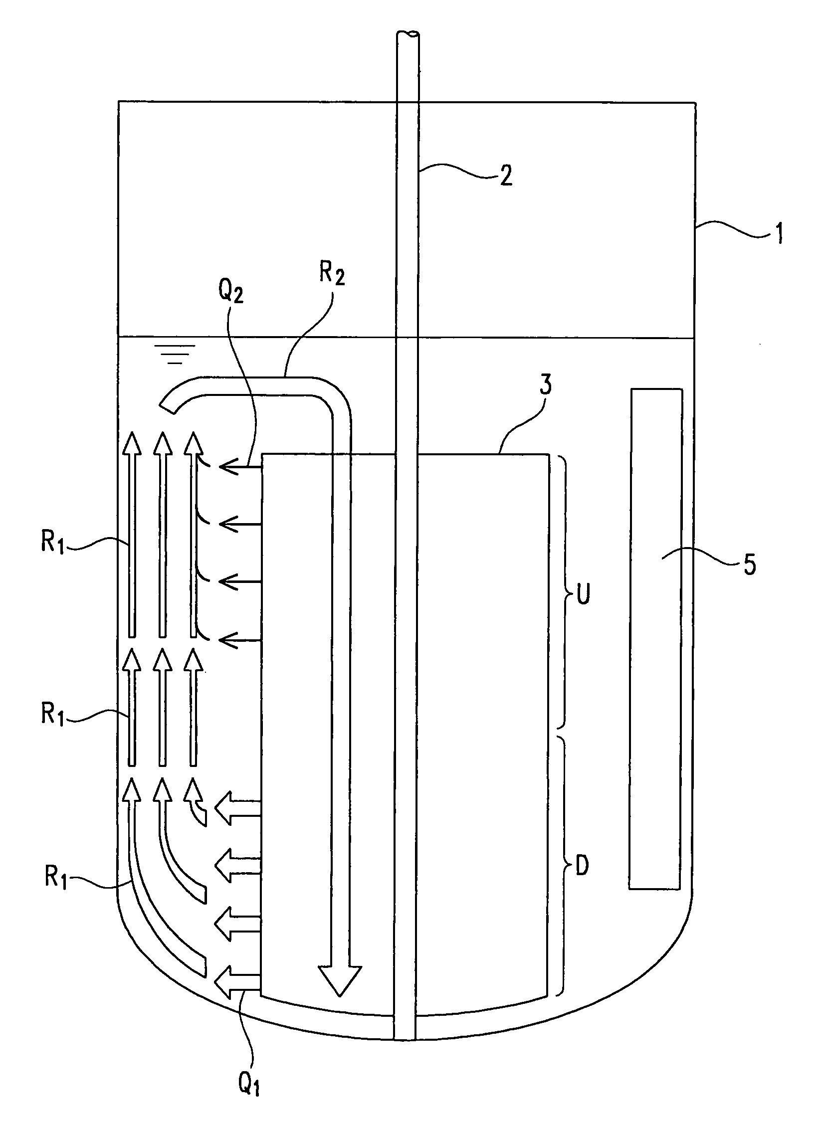
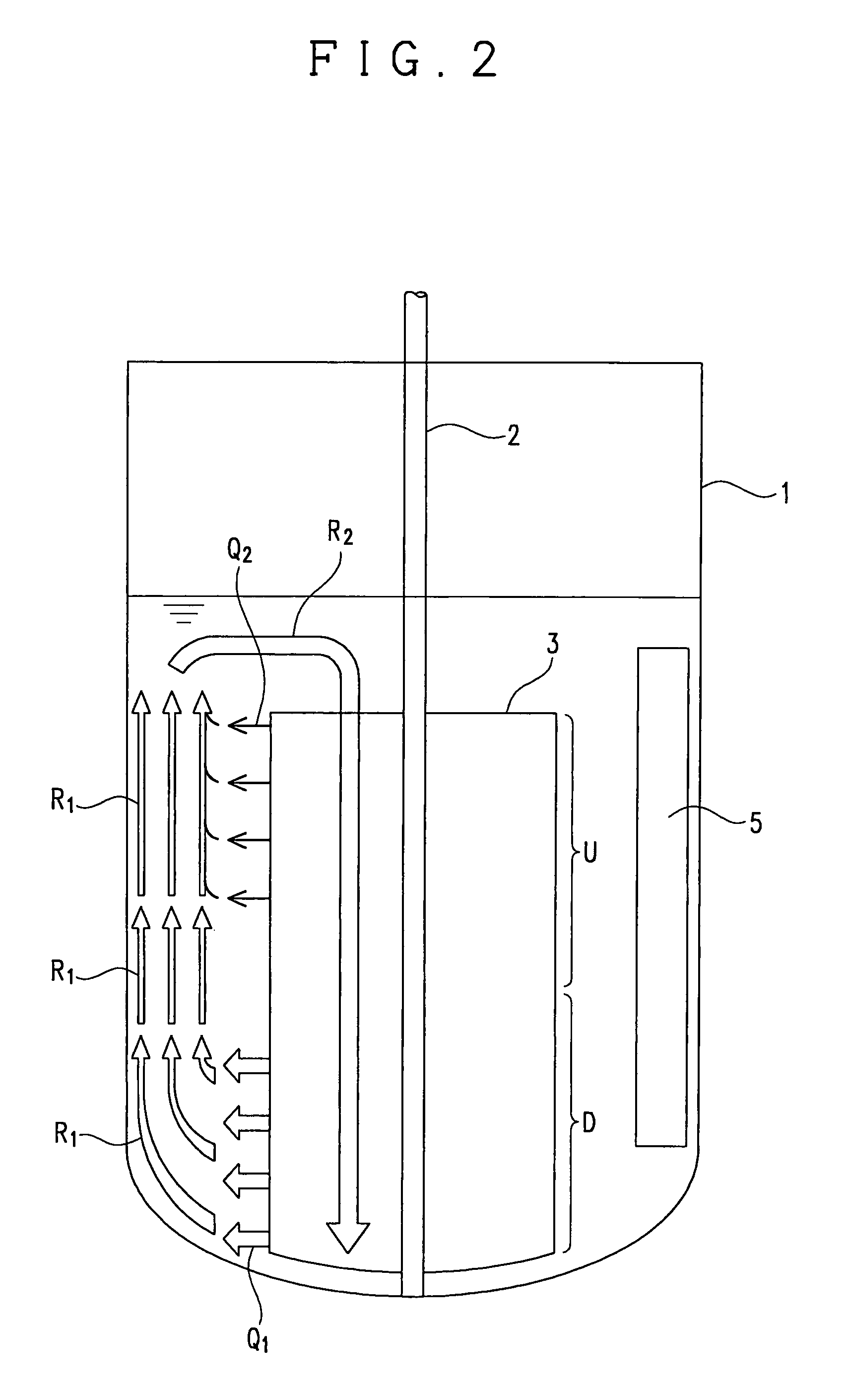
[0028]A reference numeral 1 represents a cylindrical stirred tank with a stirring shaft 2 disposed within the tank 1 along an axis thereof. The stirring shaft 2 has a lower end supported via a bearing (not shown) disposed on the tank bottom, and an upper end connected via a coupling (not shown) to a driving unit (not shown) on the top of the tank.

[0029]A reference numeral 3 represents a flat plate like stirring impeller that has plural openings 4 and a rectangular shape, and is mounted to the stirring shaft 2 along the center line of the width of the stirring impeller 3. The number of the openings 4 located in an upper half U is greater than the number of the openings 4 located in a lower half D so that the opening ratio in the upper half U of the stirring impeller 3 (the ratio of the total opening area relative to the total area (including the total op...


PUM


Abstract

A mixer capable of developing suitable stirring characteristics by forming a sufficient vertical circulation flow over the entire part of the inside of a tank, wherein an opening is formed in a stirring blade under the following conditions: (i) the ratio of the opening area of the opening in the upper half of the stirring blade to the overall area of the upper part of the stirring blade (the opening rate in the upper half of the stirring blade) is 45 to 80%, (ii) the ratio of the opening area of the opening in the lower half of the stirring blade to the overall area of the lower half of the stirring blade (the opening rate in the lower half of the stirring blade) is 18 to 50%, and (iii) the ratio of the opening rate in the lower half of the stirring blade to the opening rate in the upper half of the stirring blade is 31 to 71%.

Description

TECHNICAL FIELD[0001]The present invention relates to a stirring apparatus that is intended to be used for mixing, dissolution, crystallization, reaction, etc.BACKGROUND ART[0002]Hitherto, there are many cases where small-sized blades, such as turbine blades, paddle blades and propeller blades are disposed at multiple stages when in use as a stirring impeller of a stirring apparatus. According to a stirring apparatus using these blades, the rate of the fluid flow pumped in the radial direction from the blades is increased by increasing the rotational speed of the impeller, so that the fluid strikes against a tank wall, and then turns upwards and downwards, thereby creating a circulation flow returning again to the impeller, and thus mixing the inside of the tank.[0003]However, the small-sized blades hardly create a satisfactory vertical circulation flow throughout the inside of the tank, as illustrated in FIG. 14, and thereby creating plural isolated zones in the vertical direction,...

Claims


Application Information

Patent Timeline
Patent Type & Authority Patents(United States)
IPC IPC(8): B01F7/32B01F7/20B01F27/906B01F27/96
CPCB01F7/003B01F7/00633B01F7/1675B01J19/0066B01J2219/00779B01F2215/0477B01J2219/00768B01F2215/0431B01F27/11251B01F27/191B01F27/86B01F27/00B01F27/80B01F27/90
Inventor YATOMI, RYUICHIMORINAGA, SHOJI
Owner SUMITOMO HEAVY IND PROCESS EQUIP CO LTD
Why Eureka
Try Eureka