
Angle adjusting device and image forming apparatus

a technology of angle adjustment and image forming apparatus, which is applied in the direction of lighting support devices, washstands, instruments, etc., can solve the problems of insufficient implementation of the angle adjustment of the operations panel, degrading the visibility of (the ability to view) the operations panel, etc., and achieves the effect of simple operation, good visibility and operability of the operations panel

Inactive Publication Date: 2011-05-03
APPLERA +1
View PDF14 Cites 1 Cited by
  • Summary
  • Abstract
  • Description
  • Claims
  • Application Information

AI Technical Summary

Benefits of technology

[0009]It is also an object of the present invention is to provide an angle adjusting device whereby an operations panel can be set at an angle for a user by a simple operation without making the size of the device large.
[0010]It is also an object of the present invention is to provide an image forming apparatus whereby good visibility and operability of the operations panel can be secured.

Problems solved by technology

However, if the operations panel is fixed, unexpected image may be generated due to positional relationship between a viewpoint of the user and a lighting apparatus in a room, so that visibility of (ability to view) the operations panel may be degraded.
Therefore, it is not always sufficiently implemented that an angle of the operations panel is adjusted properly for every user in a case where the image forming apparatus is located in an environment where the public can use it.

Method used


Image

  • Angle adjusting device and image forming apparatus
  • Angle adjusting device and image forming apparatus
  • Angle adjusting device and image forming apparatus

Examples


Embodiment Construction

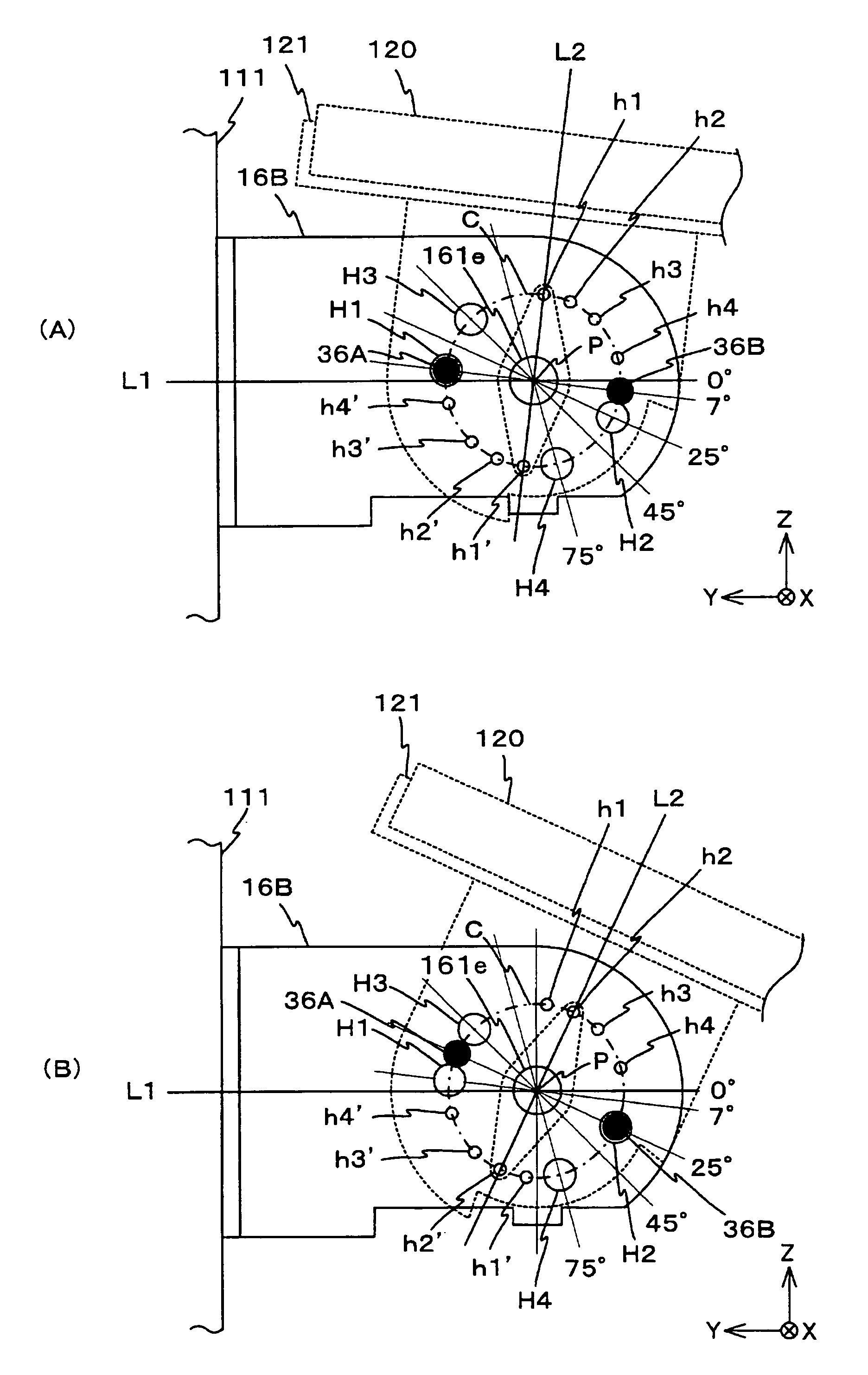
[0048]A description of the present invention is now given, with reference to FIG. 1 through FIG. 10, including embodiments of the present invention.

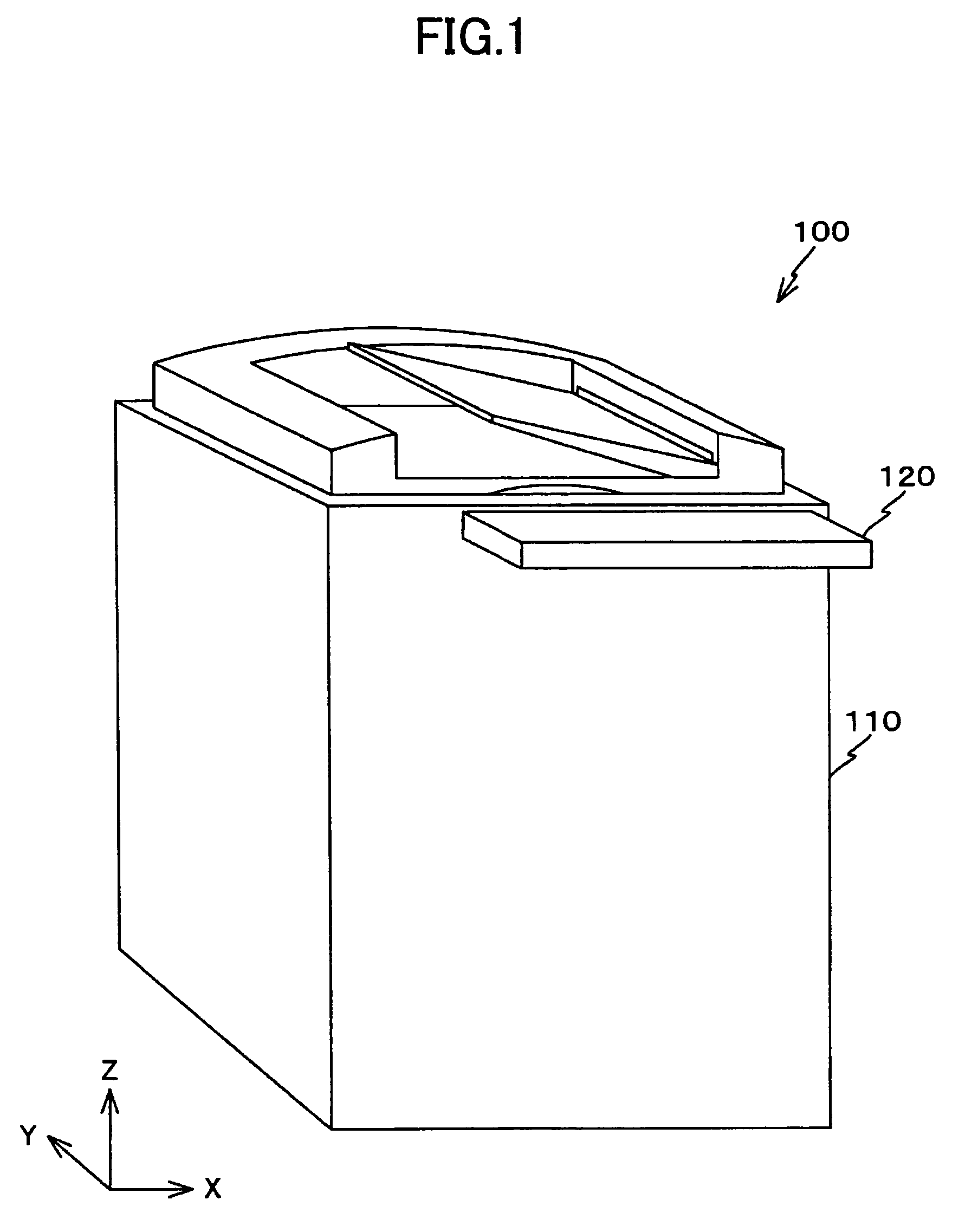
[0049]FIG. 1 is a perspective view of a copier 100 as an image forming apparatus of an embodiment of the present invention. The copier 100 includes an operations panel 120, a copier main body 110, and others. The operations panel 120 has an interface by which an user can input a command. The copier main body 110 has a substantially rectangular parallelepiped-shaped configuration. Based on the command input via the operations panel, an image of a manuscript that is a subject of copying is read out so as to be transferred to a paper by the copier main body 110.

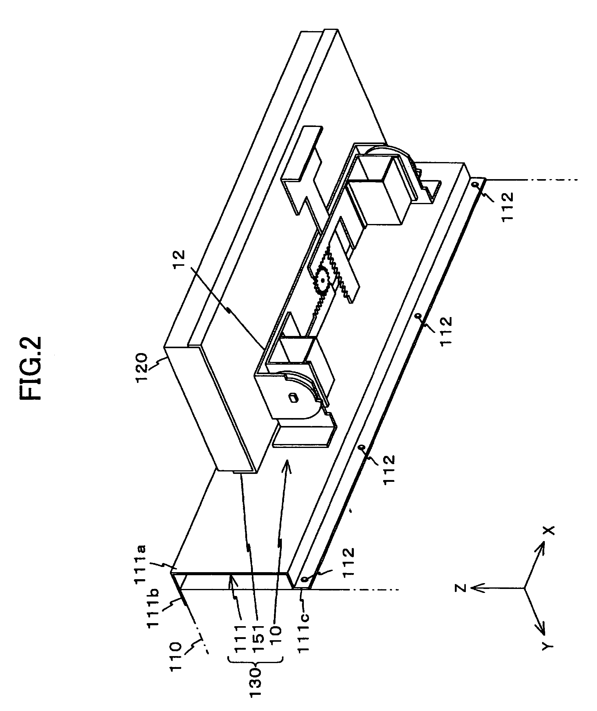
[0050]FIG. 2 is a perspective view of an angle adjusting mechanism configured to support an operations panel 120 of the copier 100 shown in FIG. 1. As shown FIG. 2, the operations panel 120 is attached to the copier main body 110 via an angle adjusting device 130.

[0051]The angle adju...


PUM


Abstract

An angle adjusting device configured to support an operations panel so that up and down rotation of the operations panel against an apparatus main body can be made in a designated angle range and configured to adjust a rotational angle of the operations panel in up and down directions against the apparatus main body, the angle adjusting device includes i) a fixing member fixed to the apparatus main body, ii) a rotation member where the operations panel is provided, the rotation member being provided to the fixing member so as to be rotated with respect to a designated rotation shaft in the designated angle range, iii) a lock mechanism configured to lock rotation of the rotation member against the fixing member with respect to the rotation shaft, at one or more parts in the designated angle range, by using a force other than a frictional force between the fixing member and the rotation member, and iv) a setting mechanism configured to set a lock-on state and lock-off state of the lock mechanism.

Description

BACKGROUND OF THE INVENTION[0001]1. Field of the Invention[0002]The present invention generally relates to angle adjusting devices and image forming apparatuses, and more specifically, to an angle adjusting device configured to adjust a rotational angle of an operations panel in up and down directions against an apparatus main body and an image forming apparatus having the above-mentioned angle adjusting device.[0003]2. Description of the Related Art[0004]An operations panel is provided in recent image forming apparatuses such as a copier or a printer. A command of a user for implementing a job is input by the operations panel and a status of a main body of an image forming apparatus is displayed in the operations panel.[0005]Generally, this operations panel is fixed to a housing (main body housing) where respective structural parts of the image forming apparatus are received. However, if the operations panel is fixed, unexpected image may be generated due to positional relationship...

Claims


Application Information

Patent Timeline
Patent Type & Authority Patents(United States)
IPC IPC(8): G03G15/00
CPCB41J3/46G03G15/5016
Inventor KAWAI, MITSUHIROWATANABE, HAYATO
Owner APPLERA
Learn More