Reduction of muzzle jump in firearms

a technology for firearms and muzzle jumps, applied in the field of firearms muzzle jump reduction, can solve the problems that the previous art is not capable of significantly suppressing the muzzle jump, and achieve the effects of reducing the muzzle jump, and reducing the amount of muzzle jump

Inactive Publication Date: 2011-05-10
LEVIN YURI S
View PDF13 Cites 3 Cited by
  • Summary
  • Abstract
  • Description
  • Claims
  • Application Information

AI Technical Summary

Benefits of technology

[0005]The above objective is achieved by creating a momentum, rotating in the direction opposite to the rotational direction of the momentum causing muzzle jump by redirecting not gas flow produced by a blast of ammunition but redirecting a projectile traveling through the barrel. For this purpose in one embodiment a barrel of a gun or of a weapon system is bent in such a way that a longitudinal axis of the bent barrel is lying in a plane, perpendicular to a weapon system supporting surface; while an arc of the longitudinal axis of the bent barrel is convex in relation to the weapon system supporting surface. This plane usually has vertical orientation. In a process of firing, the projectile due to its inertia is supposed to move straight so it is pressing at a wall of the bent barrel and the wall is responding with a centripetal force causing the projectile to deviate from its straight direction due to the bend of the barrel. In accordance to Newton Law this centripetal force is equal to an “anticentripetal” force acting on the barrel in an opposite direction. This “anticentripetal” force creates a momentum rotating in the direction opposite to the rotational direction of the momentum created by the recoil force. In previous art the redirection of the gases is usually performed near an exiting end of the barrel for a maximum utilization of the expanding gases force and for delivering maximum energy to the projectile, at the same time achieving a maximum leverage for creating the maximum contra-momentum. A kinetic energy of the projectile is increasing during its travel through the barrel while a potential energy of the expanding gases is diminishing. Besides, only a portion of the gases could be redirected for producing the contra-momentum since part of them flow through the muzzle in the same direction as the projectile does. Also the mass of the redirected gases is considerably less than the mass of the projectile. For all those reasons previous art is not capable to significantly suppress the muzzle jump. In consideration of all of the above, utilization of proposed embodiment would provide for significantly more efficient muzzle jump reduction.
[0010]Turning the housing on the barrel and securing it in a new position allows a setting up of a resulting curvature plain in such a way (usually vertically) that it would coincide with the weapon system supporting point or it would be perpendicular to the system supporting surface, which means that the resulting momentum would be positioned in the same plane as the momentum causing jump of the barrel (as it was mentioned earlier, resulting momentum has the rotational direction opposite to the rotational direction of the momentum causing jump).
[0011]A specific modification of the mounting means of the device would allow attaching it to a specific gun barrel, and adjustment of the angle between elongated axes of the housing and of the director would allow providing an appropriate contra-momentum for a specific gun. This would make it possible to use the same principal design for the multitude of the weapon systems.
[0012]It is understood that the proposed design would cause extensive wear of the barrel in case of the first embodiment or of the attachment director in case of the preferred embodiment. For this reason implementation of the attachable device may have the most practical sense because a replacement of worn-out director of the attachment is a simple enough and more cost effective operation than replacement of the worn-out barrel which would require spending significantly more money on parts and labor.

Problems solved by technology

For all those reasons previous art is not capable to significantly suppress the muzzle jump.

Method used


Image

  • Reduction of muzzle jump in firearms
  • Reduction of muzzle jump in firearms
  • Reduction of muzzle jump in firearms

Examples


Embodiment Construction

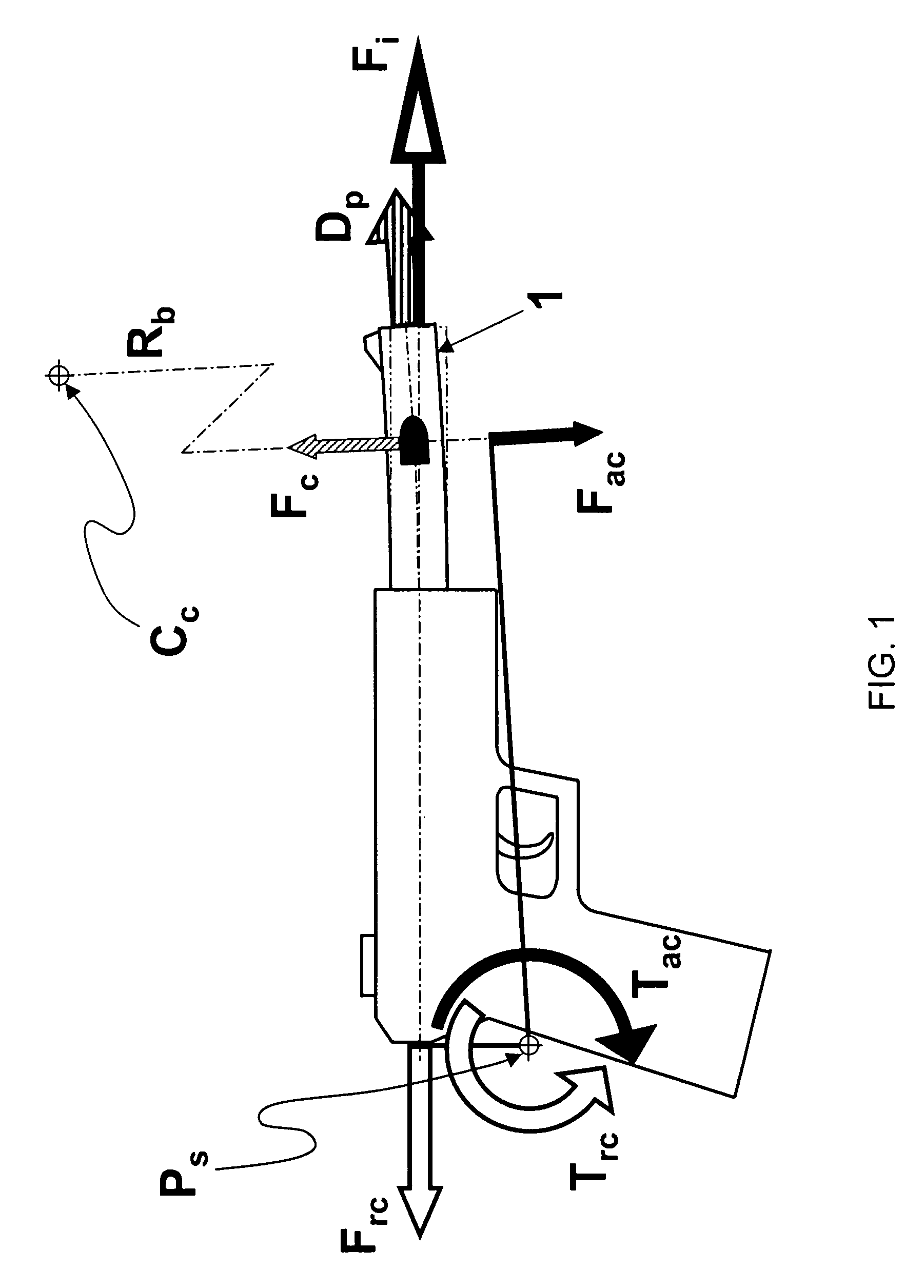
[0025]With reference now to the FIG. 1 of the drawings in preferred embodiment a barrel 1 of the weapon is bent with radius Rb in such a way that the longitudinal arched axis of the barrel 1 is laying in the plane coinciding with the weapon system's point of support Ps or it is perpendicular to a weapon system supporting surface (not shown), while the curvature of the longitudinal arched axis of the barrel 1 is convex in relation to the weapon system point of support Ps or to the weapon system supporting surface (not shown), said plane also coincides with a centre Cc of said curvature, while the longitudinal arched axis of the barrel 1 is laying in said plane between the centre Cc of the curvature and the weapon system point of support Ps or the weapon system supporting surface (not shown). This said plane is usually vertically oriented and in our case is parallel to the drawing paper plane. In the process of firing, the projectile due to its inertia force Fi is pressing at the wall...


PUM


Abstract

Muzzle jump of projectile-firing guns and weapons systems is significantly reduced by creating a momentum, rotating in the direction opposite to the rotational direction of the momentum causing muzzle jump by redirecting not a gas flow produced by a blast of ammunition but redirecting a projectile traveling through the barrel. The barrel is bent in such a way that curvature of the bend is convex in relation to the support of the gun. The plane of the curvature coincides with the plane of the momentum created by recoil of the gun. Since the projectile possesses significantly greater mass than escaping gases, the contra-momentum is greater than what could be achieved by redirecting a flow of escaping gases so it could be sufficient to completely negate momentum created by recoil force.

Description

[0001]The present invention relates to firearms and more particularly to a method and device for reduction of a gun or weapon system jump, resulting from momentum created by the recoil force developed in the process of firing.BACKGROUND OF THE INVENTION[0002]The disadvantage of known projectile firing guns and weapon systems is that each firing creates a recoil force not directed through the system support. The system support is usually located lower then the line representing the direction of the recoil force. Resulting momentum inevitably causes more or less noticeable movement of the system, for example human firing the pistol or tank firing the gun. Particularly it causes up movement (jump) of the weapon muzzle. This is the undesirable effect of firing since it creates a multitude of problems, for example, a necessity to build a heavier weapon for achieving at least partial inhibition of the jump and a necessity of spending extra time for restoring alignment of the weapon with t...

Claims


Application Information

Patent Timeline
Patent Type & Authority Patents(United States)
IPC IPC(8): F41A21/38
CPCF41A21/38
Inventor LEVIN, YURI S.
Owner LEVIN YURI S
Why Eureka
Try Eureka