
Methods and devices for moving trench grates

a trench grates and trench technology, applied in the direction of roof drainage, hoisting equipment, water-power plants, etc., can solve the problems of stepping into the opening, dragging the movers, and dragging the movers, so as to reduce the load required, reduce the load, and facilitate the movement of the trench grates.

Inactive Publication Date: 2007-12-27
MCAFEE RALPH GLENN
View PDF9 Cites 0 Cited by
  • Summary
  • Abstract
  • Description
  • Claims
  • Application Information

AI Technical Summary

Benefits of technology

[0006] To overcome the difficulties set forth above and others, the present inventor has provided a novel device that makes the movement of trench grates significantly easier.
[0007] More specifically, the present invention includes a device for moving a trench grate that includes at least: (a) a frame; (b) a dual-contact hook for attachment to a grate, the hook hanging from a part of the frame and positioned between a point of contact and a suspension point such that significant leverage is available to reduce a load required to move a grate; and (c) a plurality of swivel wheels attached to a lower section of the frame used to move the device.

Problems solved by technology

This method is both tedious, and cumbersome, not to mention the risk of back injury to the movers, stepping into the opening, or dropping the grate on someone's toes.

Method used


Image

  • Methods and devices for moving trench grates
  • Methods and devices for moving trench grates
  • Methods and devices for moving trench grates

Examples


Embodiment Construction

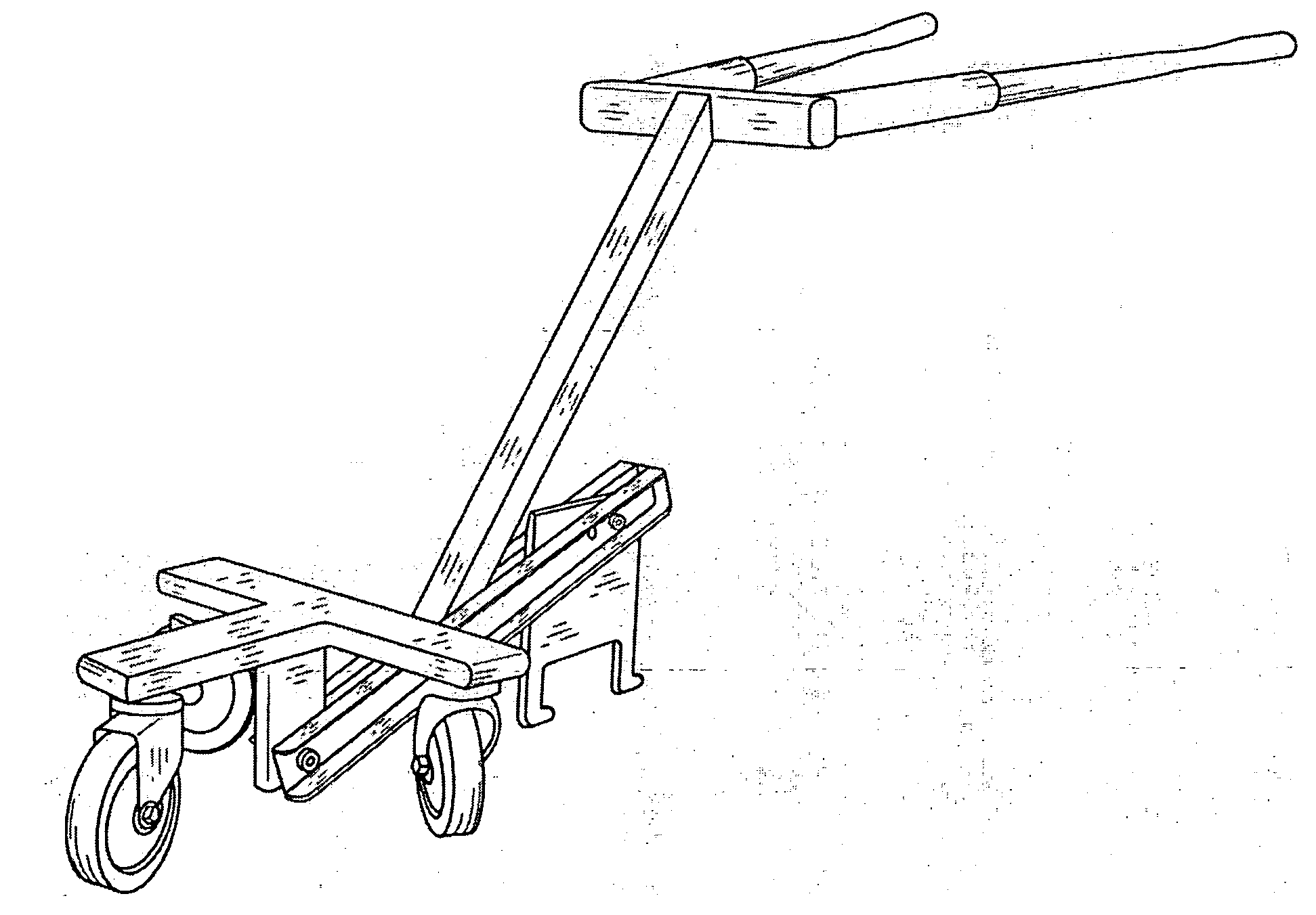
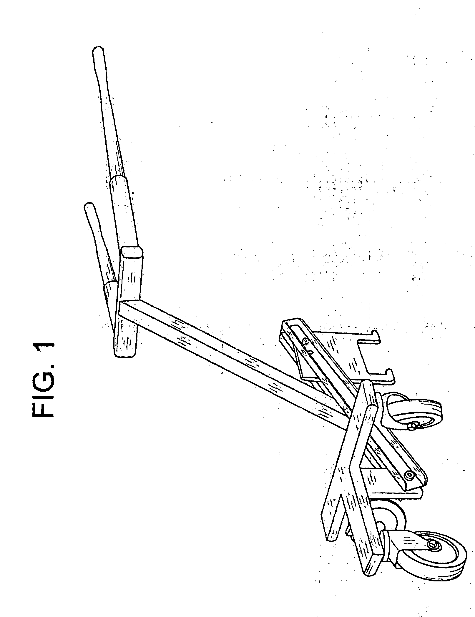
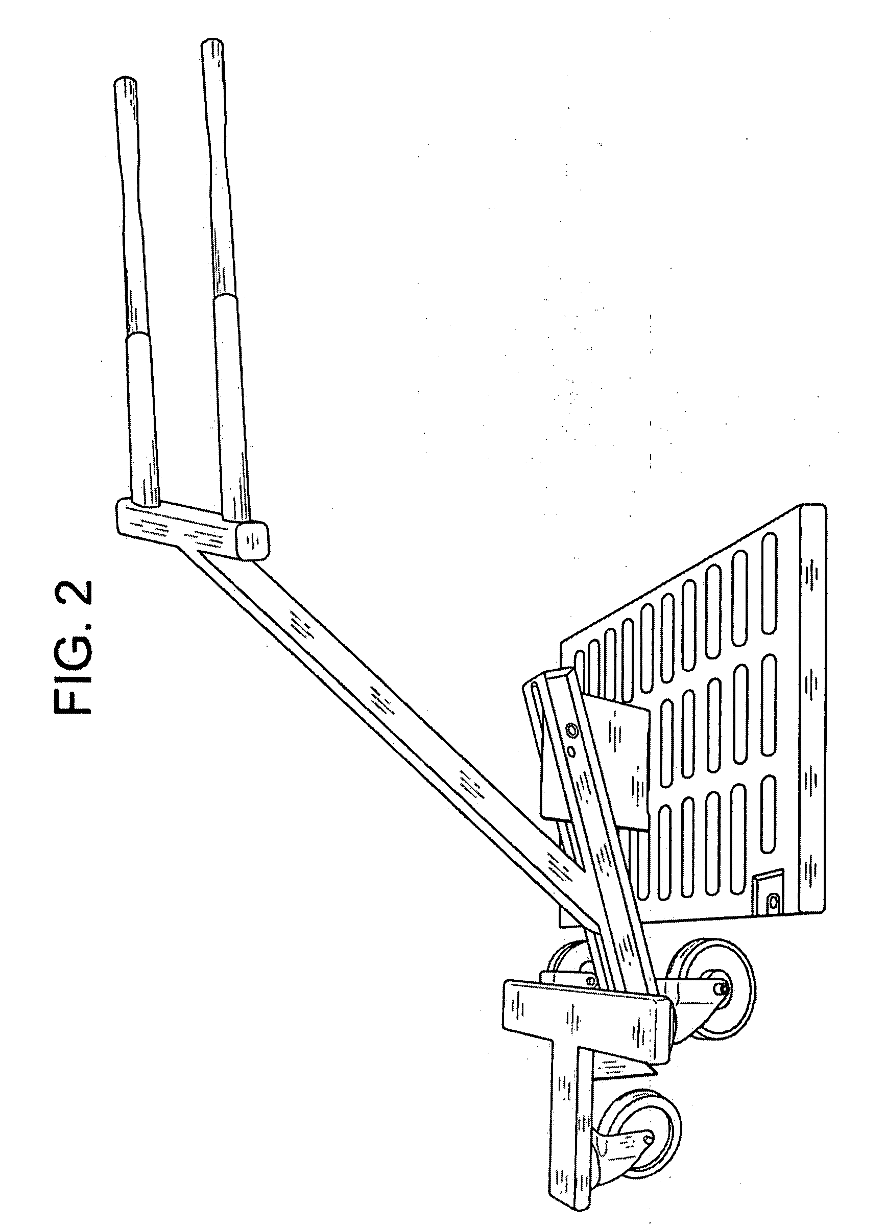
[0010] Referring to FIG. 1, there is shown a picture of a device 1 for moving a trench grate according to one embodiment of the present invention.

[0011] A shown, the device 1 includes a pair of handles 3,4 extending from a frame 5, which is suspended from a mid-point 6 in a three swivel wheeled, lower frame arrangement 7 (e.g., dolly). This suspension allows the handle frame 5 to be raised, and lowered, while still maintaining three wheel contact with the floor. This allows the plurality of wheels 8 on the lower section of the frame to swivel freely, regardless of the handle elevation.

[0012]FIG. 1 also depicts a dual-contact hook 9 hanging from the frame 5, at an approximated one third distance between a physical point of contact on a handle, and a suspension point (on the lower frame or dolly). This hook 9 is designed to fit within a specific grate (i.e., grate pattern) so as to ensure contact at two points (for stability). As the reader will surmise, because of this the hook 9 s...


PUM


Abstract

A novel device makes the movement of trench grates significantly easier. The device is advantageously designed to provide significant leverage, leverage that is needed to move heavy trench grates.

Description

RELATED APPLICATION [0001] This application is related to, and claims the benefit of priority from, U.S. Provisional Patent Publication No. 60 / 811447 filed on Jun. 7, 2006 the contents of which are incorporated in full herein as if set forth in full herein.BACKGROUND OF THE INVENTION [0002] Manipulating heavy (approx. 200 lbs.) cast iron floor trench grates is a challenge. These grates are typically placed across doorways, ramps, and other entrances to hangers, warehouses, subways, etc, for drainage purposes. [0003] In some instances they are also used to contain mechanical piping, such as fire sprinkler systems, and miscellaneous plumbing. [0004] The installation and maintenance of such systems requires the periodic removal and replacement of grates. This has been done up to this point by hooking a bent rod in two places, and then having two or more people lift a grate and then do a “crab-walk” sideways across an opening to set the grate down. This method is both tedious, and cumbe...

Claims


Application Information

Patent Timeline
Patent Type & Authority Applications(United States)
IPC IPC(8): E02B5/02
CPCB66F19/005
Inventor MCAFEE, RALPH GLENN
Owner MCAFEE RALPH GLENN
Learn More