Method and system for the supply of hot direct reduced iron for multiple uses

a technology of hot direct reduction and reduced iron, which is applied in the direction of lighting and heating apparatus, charge manipulation, furniture, etc., to achieve the effects of reducing heat loss, facilitating and safe operation, and simplifying melt shop

Active Publication Date: 2011-05-10
MIDREX TECH INC
View PDF11 Cites 2 Cited by
  • Summary
  • Abstract
  • Description
  • Claims
  • Application Information

AI Technical Summary

Benefits of technology

[0010]Advantageously, the method and system of the present invention supply HDRI for multiple uses at the highest possible temperature by minimizing heat losses, allowing the HDRI to flow in a continuous and controlled manner by gravity in the closed, insulated duct system. The method and system of the present invention independently control the discharge rates of the multiple streams of HDRI by effecting the split and independent control of the discharge rates of the multiple streams of HDRI outside of the DR shaft furnace or DRI reheating furnace at or near atmospheric pressure. Thus, multiple outlets that would affect the operation of the DR shaft furnace or DRI reheating furnace are not required. The method and system of the present invention eliminate the breakage of the associated hot pellets, lumps, or agglomerates, as well as the related dust generation that occurs with pneumatic transport systems. Finally, the method and system of the present invention, in the exemplary embodiment incorporating the combination of gravity and a generally horizontal charge conveyor, reduce the overall height of the DR shaft furnace or DRI reheating furnace.
[0014]Thus, the advantages of the method and system of the present invention over conventional systems and methods include: a continuous feed to a melter charge system simplifies melt shop HDRI logistics and operations, as transport vessels, bins, and cranes are not required; a continuous feed to the melter charge system involves less heat loss than the use of transport vessels, as the transport vessels continue to lose heat when emptied, etc.; DR shaft furnace or DRI reheating furnace operation is not affected by a single discharge point, as would be the case with multiple discharge points; the split and control of streams of HDRI is easier and safer to perform while at or near atmospheric pressure than at or near DR shaft furnace or DRI reheating furnace operating pressures, as would be the case with multiple discharge points; and the gravity discharge and split of HDRI is not as complicated as the pneumatic transport of HDRI—gravity always works and pneumatic transport systems incorporate mechanical components that require regular maintenance and inherently have a lower availability.

Problems solved by technology

Some DR plants, however, are not located in or adjacent to a steelmaking complex.

Method used


Image

  • Method and system for the supply of hot direct reduced iron for multiple uses
  • Method and system for the supply of hot direct reduced iron for multiple uses
  • Method and system for the supply of hot direct reduced iron for multiple uses

Examples


Embodiment Construction

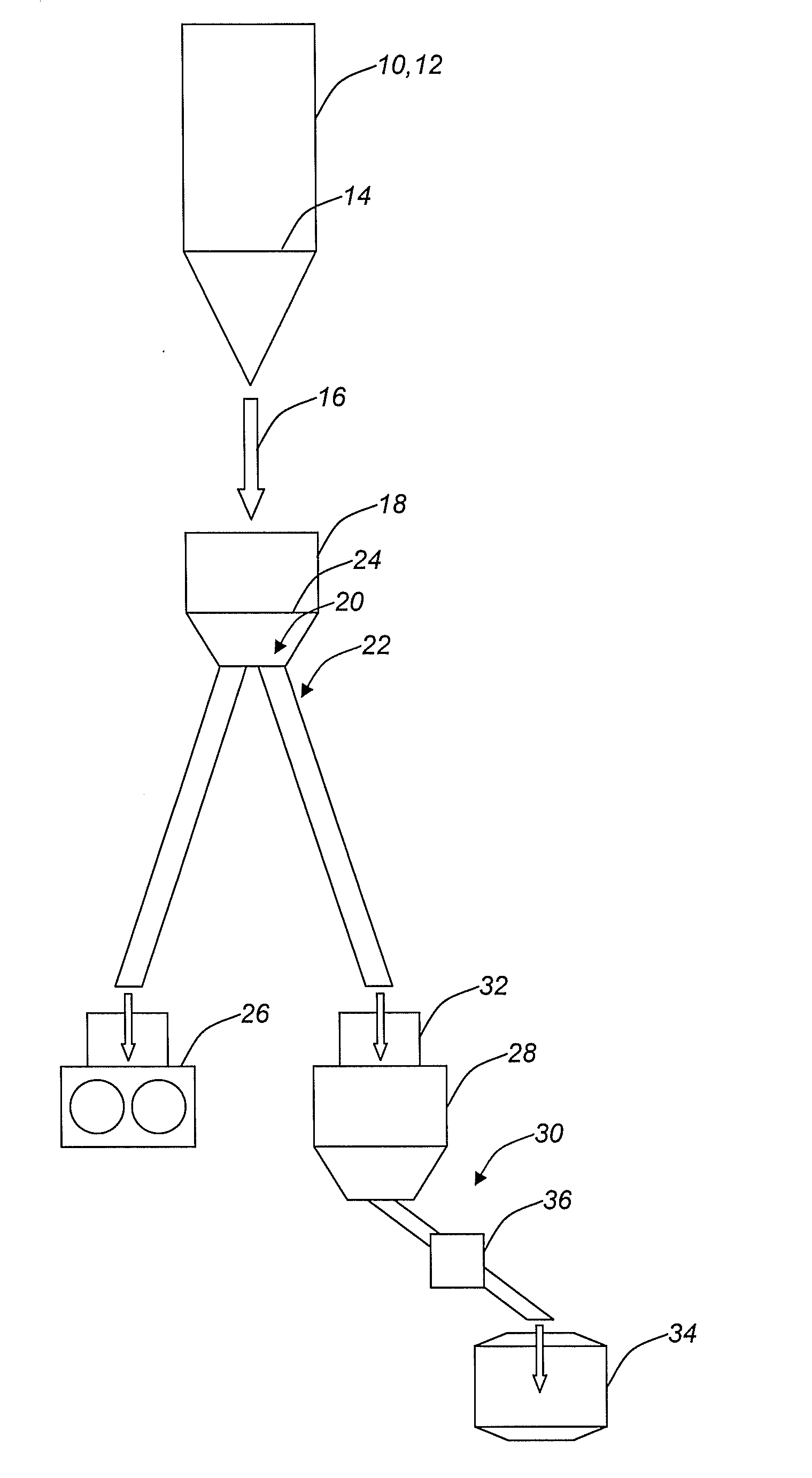
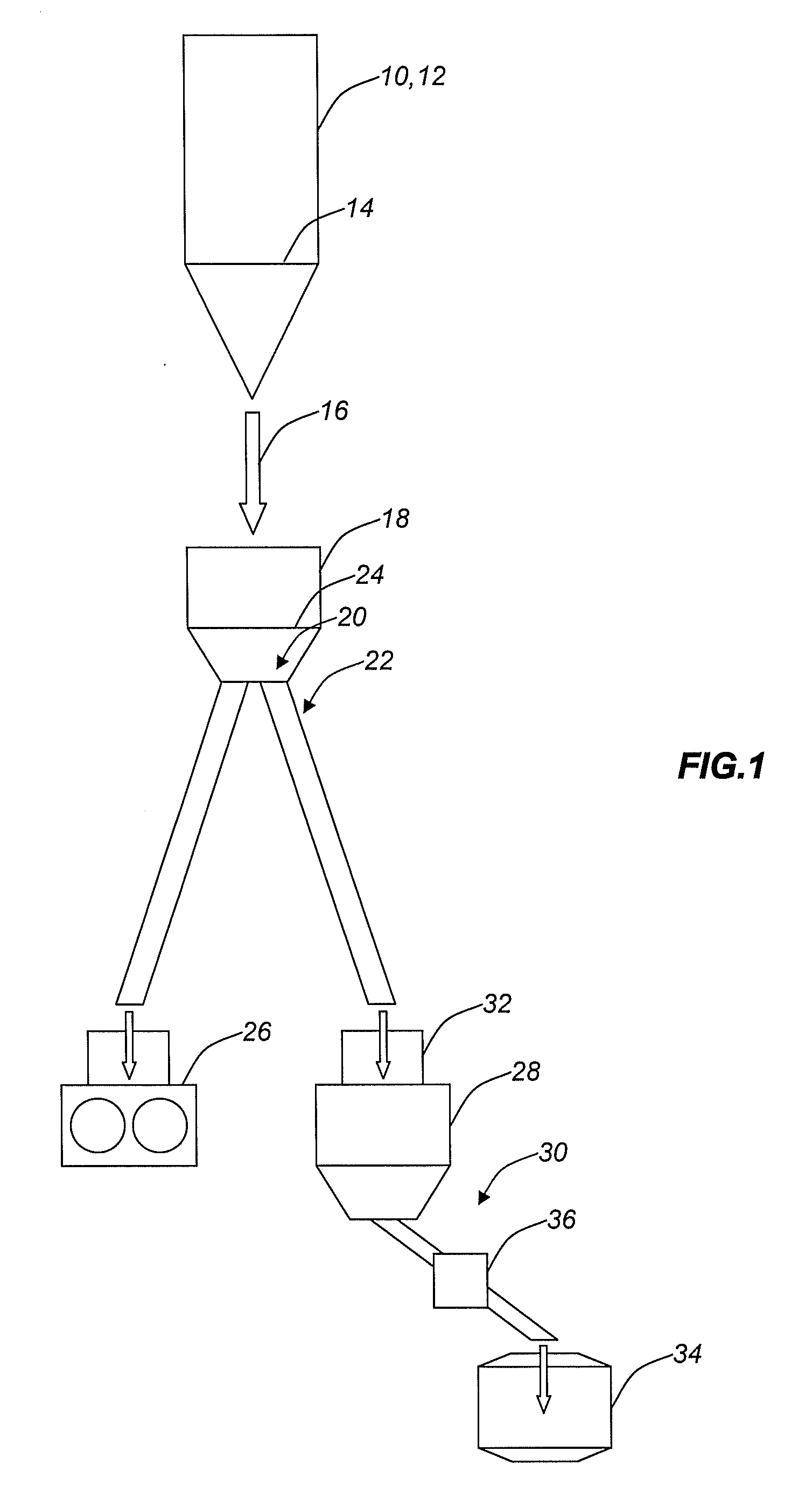
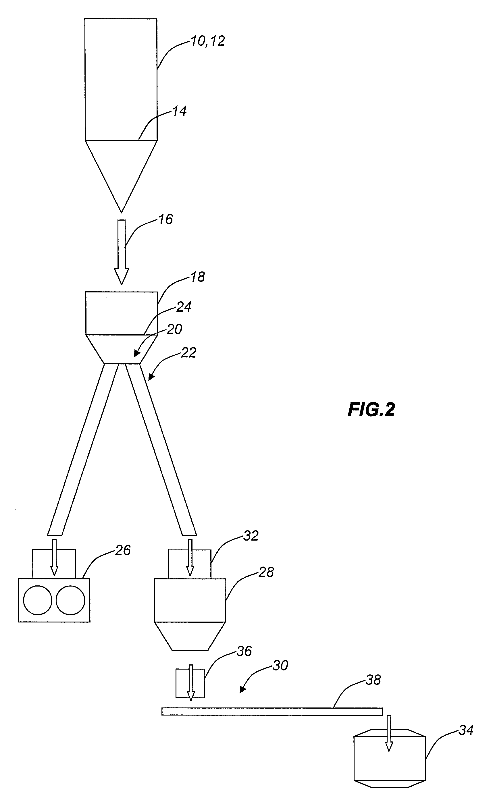
[0019]Referring now to FIGS. 1-3, hot direct reduced iron (HDRI) is produced by reducing iron oxide pellets, lumps, and / or agglomerates in a direct reduction (DR) shaft furnace 10. HDRI is also produced by reheating cold direct reduced iron (DRI) pellets, lumps, and / or agglomerates in a DRI reheating furnace 12.

[0020]In the case of the DR shaft furnace 10, the DR shaft furnace 10 is used to reduce the iron oxide with a countercurrent flow of reducing gas, consisting primarily of carbon monoxide and hydrogen. This reducing gas may be made from natural gas or other gaseous fuels, solid fuels, such as coal, or liquid fuels, such as heavy fuel oil. The HDRI descends as a moving packed bed through the DR shaft furnace 10 by gravity. The DR shaft furnace 10 has a converging discharge section 14 that ends as a point outlet through which all of the HDRI is continuously discharged.

[0021]In the case of the DRI reheating furnace 12, the design fundamentals described above are essentially the s...


PUM

PropertyMeasurementUnit
gravityaaaaaaaaaa
pressure dropaaaaaaaaaa
temperaturesaaaaaaaaaa

Abstract

The present invention relates generally to a method and system for the supply of a continuous stream of hot direct reduced iron (HDRI) from a direct reduction (DR) shaft furnace or direct reduced iron (DRI) reheating furnace to a point outside of the DR shaft furnace or DRI reheating furnace where the HDRI stream is split into at least two HDRI streams. The first HDRI stream is sent continuously to a hot briquetting plant by gravity in a closed duct system. The second HDRI stream is sent continuously to an adjacent melting furnace also by gravity in a closed duct system, with a surge bin and feeders, or by a combination of gravity in a closed duct system, also with a surge bin and feeders, and a generally horizontal charge conveyor. Optionally, a third HDRI stream is employed to continuously feed multiple hot transport vessels.

Description

CROSS-REFERENCE TO RELATED APPLICATION[0001]The present non-provisional patent application claims the benefit of priority of U.S. Provisional Patent Application No. 60 / 921,539, filed on Apr. 2, 2007, and entitled “METHOD AND SYSTEM FOR THE SUPPLY OF HOT DIRECT REDUCED IRON FOR MULTIPLE USES,” the contents of which are incorporated in full by reference herein.FIELD OF THE INVENTION[0002]The present invention relates generally to a method and system for the supply of a continuous stream of hot direct reduced iron (HDRI) from a direct reduction (DR) shaft furnace or direct reduced iron (DRI) reheating furnace to a point outside of the DR shaft furnace or DRI reheating furnace where the HDRI stream is split into at least two HDRI streams. The first HDRI stream is sent continuously to a hot briquetting plant by gravity in a closed duct system. The second HDRI stream is sent continuously to an adjacent melting furnace also by gravity in a closed duct system, with a surge bin and feeders, ...

Claims


Application Information

Patent Timeline
Patent Type & Authority Patents(United States)
IPC IPC(8): C21B13/02
CPCC21B13/0086C21B13/14C21B13/143F27D3/10F27B1/005F27B19/04F27D3/0033C21C5/527C21B2100/44C21B2100/66C21B2100/26Y02P10/134Y02P10/20Y02P10/25
Inventor METIUS, GARY EDWARDMONTAGUE, STEPHEN CRAIGKAKALEY, RUSSELL
Owner MIDREX TECH INC
Why Eureka
Try Eureka