Compact display flex and driver sub-assemblies

a flexible circuit and driver technology, applied in the direction of optics, printed circuit aspects, instruments, etc., can solve the problems of increasing the size of the space within the device becoming increasingly limited, and the electronic device and the display being increasingly smaller. , to achieve the effect of less space, narrower width and less spa

Active Publication Date: 2011-05-10
APPLE INC
View PDF2 Cites 5 Cited by
  • Summary
  • Abstract
  • Description
  • Claims
  • Application Information

AI Technical Summary

Benefits of technology

[0004]The present invention can include compact flex and driver sub-assemblies for an electronic device. The compact sub-assemblies can reduce the amount of space occupied by the flex, the driver, and the wires that operatively couple the two components.
[0005]In one or more embodiments of the present invention, this can be accomplished by providing a flex with one or more attachment portions that attach to previously unused areas on a substrate on which the driver is disposed. This can reduce or eliminate the areas of the substrate to which the flex used to be attached in conventional designs. For example, in conventional display assemblies, some areas of the substrate disposed laterally adjacent to the driver may not be occupied by other components. Thus, the flex can be attached to those areas of the substrate. Wires can be disposed in a multi-dimensional (e.g., 2-D or 3-D) pattern on the substrate to operatively couple the driver to portion(s) of the flex attached to the substrate.
[0006]In one or more embodiments of the present invention, the space within the electronic device occupied by the flex and driver sub-assembly can be reduced by reducing the maximum width of the flex to be less than that of the driver. To evenly distribute and balance the signal lines across the entire width of the driver, one or more of the wires that operatively couple the flex to the driver can be run underneath the driver. Thus, at least one wire can be disposed in an area of the substrate on which the driver also is to be disposed, directly or indirectly.
[0007]Another embodiment of the present invention can include staggered wire layouts that facilitate coupling of a flex to a substrate when the wires on both components are not co-linearly disposed with each other at or near the regions in which the two components are attached.

Problems solved by technology

Consumers are demanding increasingly smaller electronic devices with increasingly larger displays.
Consequently, space within the devices has become increasingly limited.
In particular, the size of the electronic device and display can be limited, in part, by the space occupied by the display driver, the flex, and the wires that operatively couple the two components.

Method used


Image

  • Compact display flex and driver sub-assemblies
  • Compact display flex and driver sub-assemblies
  • Compact display flex and driver sub-assemblies

Examples


first embodiment

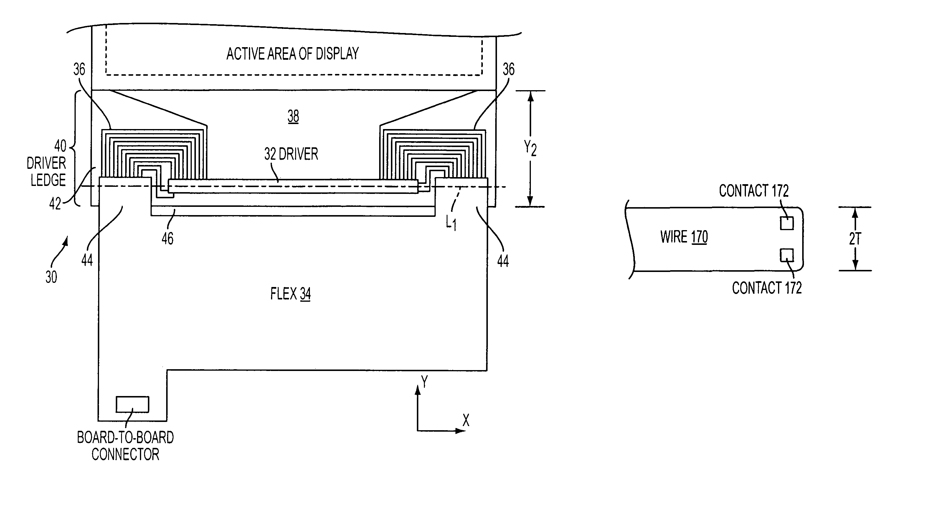
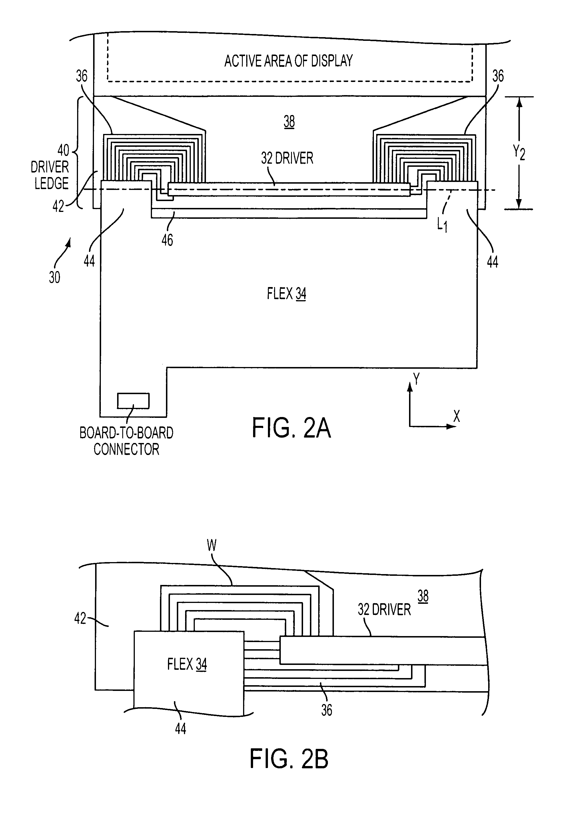
[0028]FIGS. 2A-2B illustrate a compact flex and driver sub-assembly in accordance with the present invention. Sub-assembly 30 can include driver 32, flex 34, flex-to-driver fan-out 36, and driver-to-active area fan-out 38, all of which can be disposed (at least in part) on driver ledge 40 of pixel activation substrate 42, directly or indirectly. In one embodiment of the present invention, substrate 42 can be made of transparent, non-conductive material, e.g., glass.

[0029]To reduce the Y dimension of the driver ledge so that length Y2 of ledge 40 is less than length Y1 of ledge 24 of FIG. 1, the space on driver ledge 42 occupied by portions of flex 20 and fan-out 28 in conventional display assembly 10 can be reduced or eliminated. This can be accomplished by attaching multiple smaller attachment portions 44 of flex 34 to areas of substrate 42 that were unused in conventional display assembly 10, instead of attaching the flex to the pixel activation substrate along the entire width of...

second embodiment

[0035]FIG. 3 illustrates a compact flex and driver sub-assembly in accordance with the present invention. Flex and driver sub-assembly 50 can include driver 52, flex 54, flex-to-driver fan-out 56, and driver-to-active area fan-out 58, all of which can be disposed (at least in part) on driver ledge 60 of pixel activation substrate 62, directly or indirectly.

[0036]To reduce the space within the electronic device that is occupied by flex 54, flex 54 can have a maximum width that is less than that of flex 20 of FIG. 1 and driver 52 (i.e., maximum width X54 of flex 54 can be less than width X52 of driver 52). Because flex 54 has a smaller width, the area of flex 54 that can be attached to pixel activation substrate 62 also can be smaller. As a result, flex 54 may not be able to accommodate as many wires. Again, a high speed serial interface may be employed to permit all desired signals to be transmitted using fewer wires. Composite wires, such as those described below with respect to FIG...

third embodiment

[0039]FIG. 4 illustrates a compact flex and driver sub-assembly in accordance with the present invention. Flex and driver sub-assembly 70 can include driver 72, flex 74, flex-to-driver fan-out 76, and driver-to-active area fan-out 78 disposed on driver ledge 80 of pixel activation substrate 82, directly or indirectly.

[0040]Sub-assembly 70 can be a combination of sub-assemblies 30 and 50. For example, flex 74 can have maximum width X74 that is less than width X72 of driver 72. Because flex 74 is narrower, the attachment portion of flex 74 for attaching the flex to substrate 82 also may be smaller. This can permit flex 74 to be attached to previously unused portions of substrate 82. For example, flex 74 can be attached to substrate 72 so that the flex intersects the longitudinal axis of driver 72.

[0041]Flex-to-driver fan-out 76 also can be configured similarly to those of sub-assemblies 30 and 50. Flex-to-driver fan-out 76 can have wires that emanate from one or multiple edges of flex...


PUM

PropertyMeasurementUnit
non-conductiveaaaaaaaaaa
flexibleaaaaaaaaaa
sizeaaaaaaaaaa

Abstract

Compact sub-assemblies of flexible circuits and drivers are provided. The sub-assemblies can occupy less space in an electronic device than conventional sub-assemblies. In one or more embodiments of the present invention, the flexible circuits can be attached to or wires can be disposed on portions of the substrate that previously were unoccupied in conventional sub-assemblies. In one or more embodiments, the sub-assemblies of the present invention also can have wires disposed underneath the driver or vary the width of the wires. In one or more embodiments, the sub-assemblies of the present invention also can have composite wires that occupy less space than wires of conventional sub-assemblies, while still maintaining similar energy flux.

Description

FIELD OF THE INVENTION[0001]The present invention relates to compact flexible circuit and driver sub-assemblies for an electronic device.BACKGROUND OF THE INVENTION[0002]Many currently available electronic devices have displays that provide graphics to the user. To drive pixels of the display, a conventional display assembly can incorporate a display driver operatively coupled via wires to a flexible circuit. The flexible circuit (also referred to herein as a “flex”) can be operatively coupled to a circuit board of the electronic device using, e.g., board-to-board connectors. The circuit board can have a controller for generating signals that instruct the display driver to selectively drive pixels of the display.[0003]Consumers are demanding increasingly smaller electronic devices with increasingly larger displays. Consequently, space within the devices has become increasingly limited. In particular, the size of the electronic device and display can be limited, in part, by the space...

Claims


Application Information

Patent Timeline
Patent Type & Authority Patents(United States)
IPC IPC(8): G02F1/1345
CPCH05K1/147G02F1/1345H05K1/181Y10T29/4913H05K2201/09227H05K2201/10674H05K2201/09145
Inventor GETTEMY, SHAWN ROBERTYAO, WEICORLETT, BARRY
Owner APPLE INC
Why Eureka
Try Eureka