Open fit canal hearing device

a technology of open fit and hearing aid, which is applied in the field of hearing aid devices, can solve the problems of limiting the “open” of the flexible mounting member, and achieve the effect of less fit and reducing acoustic feedback

Active Publication Date: 2011-05-10
ANOVA HEARING LABS
View PDF21 Cites 22 Cited by
  • Summary
  • Abstract
  • Description
  • Claims
  • Application Information

AI Technical Summary

Benefits of technology

[0013]The hearing device of the present invention pertains to devices which are inserted substantially within the ear canal and is an improvement over conventional ITE (in the ear), ITC (in the canal) and CIC completely in the canal aids in that it provides a natural sounding experience with a comfortable occlusion less fit in a design which mitigates acoustic feedback.
[0014]In the present invention a case, otherwise known as a shell, is made smaller than conventional CIC aids, which are custom formed to conform to the wearer's ear canal. Specifically, the case of the present invention has a generally elliptical cross section and is of a smaller cross section than that of an average wearer's ear canal when mounted in the wearer's ear. The case of the present invention is, by design, non-conformal to the wearer's ear canal so that a gap is provided around the case between the length of the case and the wearer's ear canal. This gap provides both a comfortable fit in that the case is in minimal contact with the wearer's ear canal. In addition, occlusion, or a blocked sensation experienced by the majority of CIC / ITC / ITE users is virtually eliminated. Also, the gap allows natural sounds from the surrounding to bypass microphone and blend with the sound emanating from the receiver section. As the case is designed of smaller cross section along the entire length of the case for most individuals, an impression for a conformal fitting is not necessary, making the hearing device of the present invention amenable to mass production.
[0018]One embodiment of the invention shows a feature wherein rotatable adjusting members comprising vane or blades and the like are rotated relative to the flexible mounting member already having an open area. The adjusting member effectively blocks off more or less area and is fixed once the wearer is satisfied with the adjustment. The adjusting member can also function to complement the mounting already provided by the mounting member. In many instances, such as a dome or propeller type ear piece the adjusting member can be a substantial duplicate of the flexible member. The position of the adjusting member relative to the mounting member can be retained by placing teeth on the mating surfaces of the adjusting and mounting members so to prevent relative movement once secured by a screw or other fastening means.

Problems solved by technology

However, because of feedback issues particularly with wearer's having significant hearing losses at higher frequencies, there is a limit to how “open” the flexible mounting member can be.

Method used


Image

  • Open fit canal hearing device
  • Open fit canal hearing device
  • Open fit canal hearing device

Examples


example 1

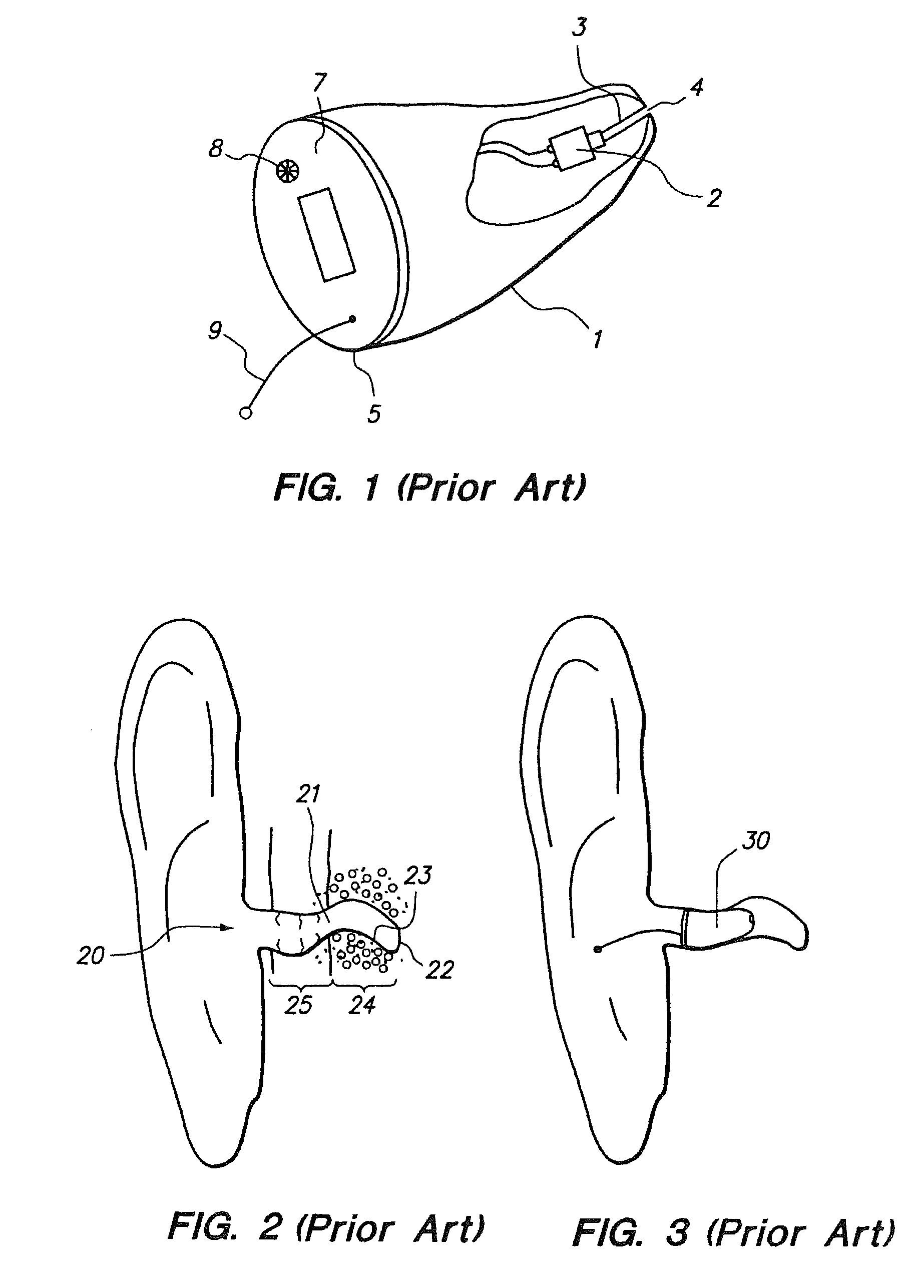
[0042]A wearer with moderate hearing loss was fitted with a custom molded conventional digital type CIC hearing aid, without active feedback control and conforming to the wearer's ear canal. The aid was vented by means of a 0.8 mm vent tube extending near the case tip and through an opening in the faceplate. The aid was then completely inserted into the wearer's ear and retained through contact with the wearer's ear canal. The aid is adjusted to provide sufficient amplification to the satisfaction of the wearer.

example 2

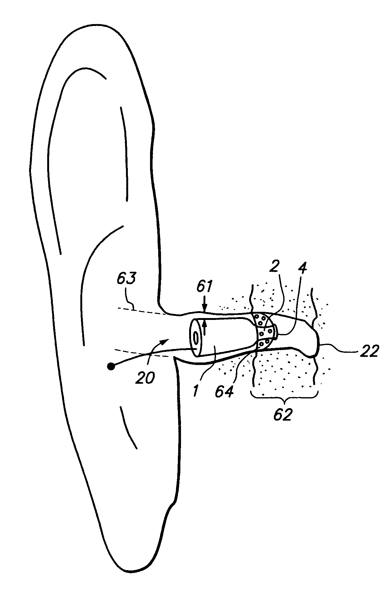
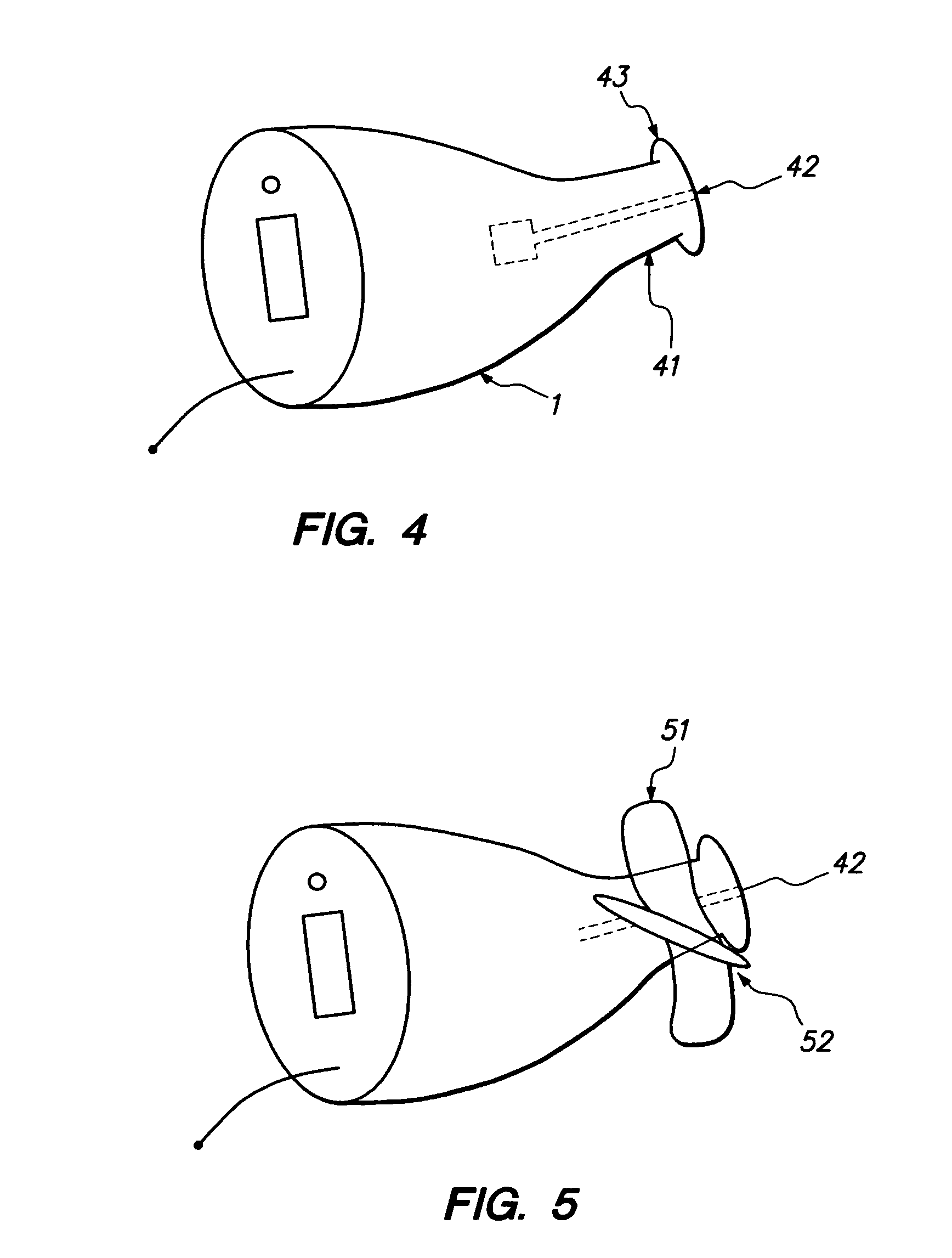
[0043]The same hearing aid circuit of Example 1 was placed in a smaller diameter case, but without the conventional vent tube arrangement described in Example 1. The case tip was then fitted with the propeller type insert 51 of FIG. 5. The open area of the propeller insert was about 50% in its unmounted state. The insert 51, was then secured in the wearer's inner ear by contact of the flexible propeller insert substantially within the bony region of the wearer's ear canal. An average air gap of about 1 mm was formed around the case and along its length. As the case is substantially concentrically mounted within the ear canal, a substantially annular gap is formed between the case and the ear canal. The propeller insert provided about 40% open area after being mounted. The wearer commented immediately on the comfort of the fit and also commented that he could hear more naturally not hearing his own voice when he talked. This aid provided 25% db of gain, without feedback.

example 3

[0044]The same hearing aid circuit and case of Example 2 was then compared using a domed insert mounted at the case tip end. The domed insert was fitted with openings around near central portion of the dome so that they would not be blocked after insertion into the wearer's ear. The open area was estimated at 25% after insertion of the aid into the wearer's ear. This aid provided a 30% improvement of gain with similar favorable responses in Example 2.


PUM


Abstract

An improved hearing aid device adapted for use within the ear canal of the CIC (Completely In the ear) and of the partially exposed ITC (In The Canal) type. This aid consists of a system of integrated parts allowing an air gap to substantially surround the hearing aid shell and air passages which communicate with the inner ear minimizing occlusion sensations and providing the user with an enhanced natural hearing experience. A key aspect of this device is the provision of air passages in the mounting insert which securely positions the hearing aid shell in the wearer's canal. These passages are designed to stay open after insertion of the aid in the ear canal. In use, unamplified sound from the outside passes around the hearing aid shell, through the air passages in the mounting insert blending with the amplified sound emanating from the receiver. The area of air passages in the mounting insert can be tailored by the technician adapting to the hearing loss characteristics of the user. Surprisingly, acoustic feedback is mitigated in spite of the openness of this novel design.

Description

FIELD OF THE INVENTION[0001]This invention relates to hearing aid devices in which the entire hearing aid including microphone, receiver, circuitry and power source are mounted substantially within the ear canal. This invention provides benefits to the ITE (In the ear), wherein the aid is partially exposed outside the ear canal, the CIC (Completely in the Canal) Aid and modifications between these types.BACKGROUND OF THE INVENTION[0002]A very thorough description of the Ear canal Anatomy is provided in published patent application Ser. No. 10 / 052,199 to Shennib et al the entirety of said specification is herein incorporated by reference.[0003]Conventional hearing devices are typically characterized by the way they fit into the individual's ear and are:[0004]1) Behind-The-Ear (BTE) type in which the main body consisting of the microphone, power source, amplifier and ear phone / receiver are mounted behind the ear and the sound tube communicating from the earphone to an ear mold which t...

Claims


Application Information

Patent Timeline
Patent Type & Authority Patents(United States)
IPC IPC(8): H04R25/00H04R25/02A61B7/02
CPCH04R25/656H04R2225/023H04R2460/09
Inventor CALDAROLA, JAMES F.
Owner ANOVA HEARING LABS
Why Eureka
Try Eureka