
Window drain

a technology for windows and drains, applied in the field of windows and drains, can solve the problems of impaired appearance at the proximity difficult installation and fixing of the correct position of the window drain, etc., and achieve the effect of improving the appearance of the window drain and the proximity thereof, improving the appearance, and improving the appearan

Inactive Publication Date: 2011-05-17
NICHIHA CORP
View PDF32 Cites 0 Cited by
  • Summary
  • Abstract
  • Description
  • Claims
  • Application Information

AI Technical Summary

Benefits of technology

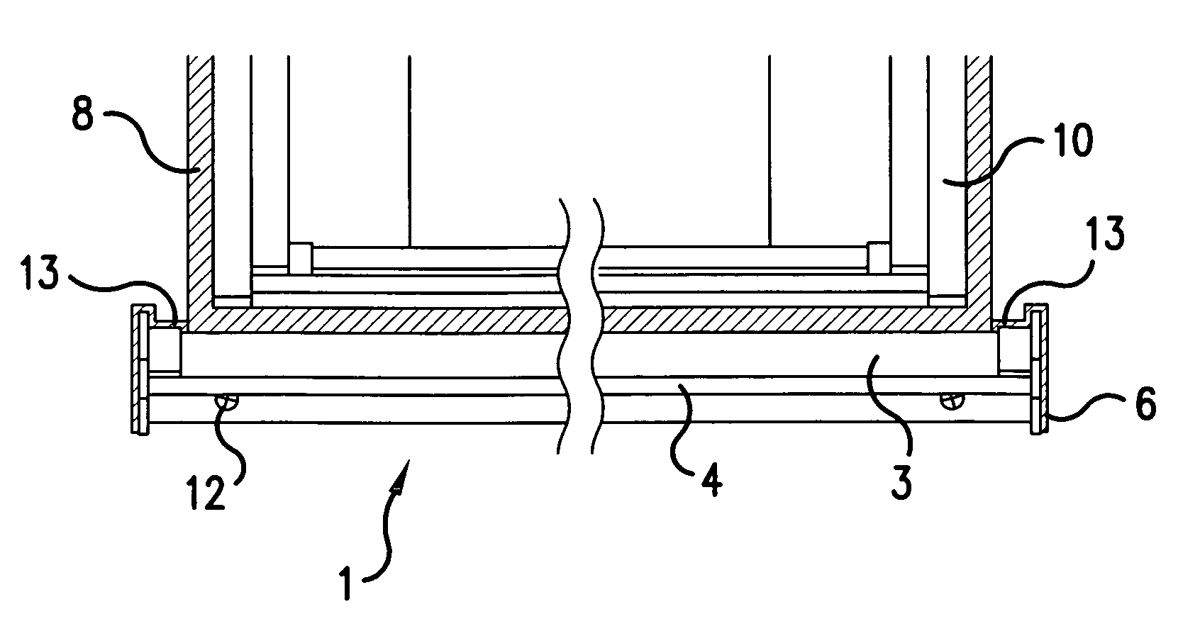
The present invention provides a window drain that can be installed and sealed more easily, preventing stains caused by rain drops and damage caused by frozen water without impairing the appearance of a building. The window drain has a horizontal portion for latching itself to an upper portion of an external wall, a sloping portion extending downwardly from the horizontal portion, a vertical portion extending downwardly from the upper portion of the sloping portion, and a front portion extending downwardly from the lower end of the sloping portion. The window drain also has upstanding portions at both ends to regulate a stream of water and prevent stains on an external wall caused by rain water and damage caused by frozen water.

Problems solved by technology

Consequently, two (2) sealing portions are visible and the appearance at the proximity of the window drain is impaired.
Such a process is troublesome, and also it is difficult to install and fix a window drain in the correct position.

Method used


Image

  • Window drain
  • Window drain
  • Window drain

Examples


example 1

[0020]An example of a procedure for installing a window drain in accordance with the present invention is explained below.

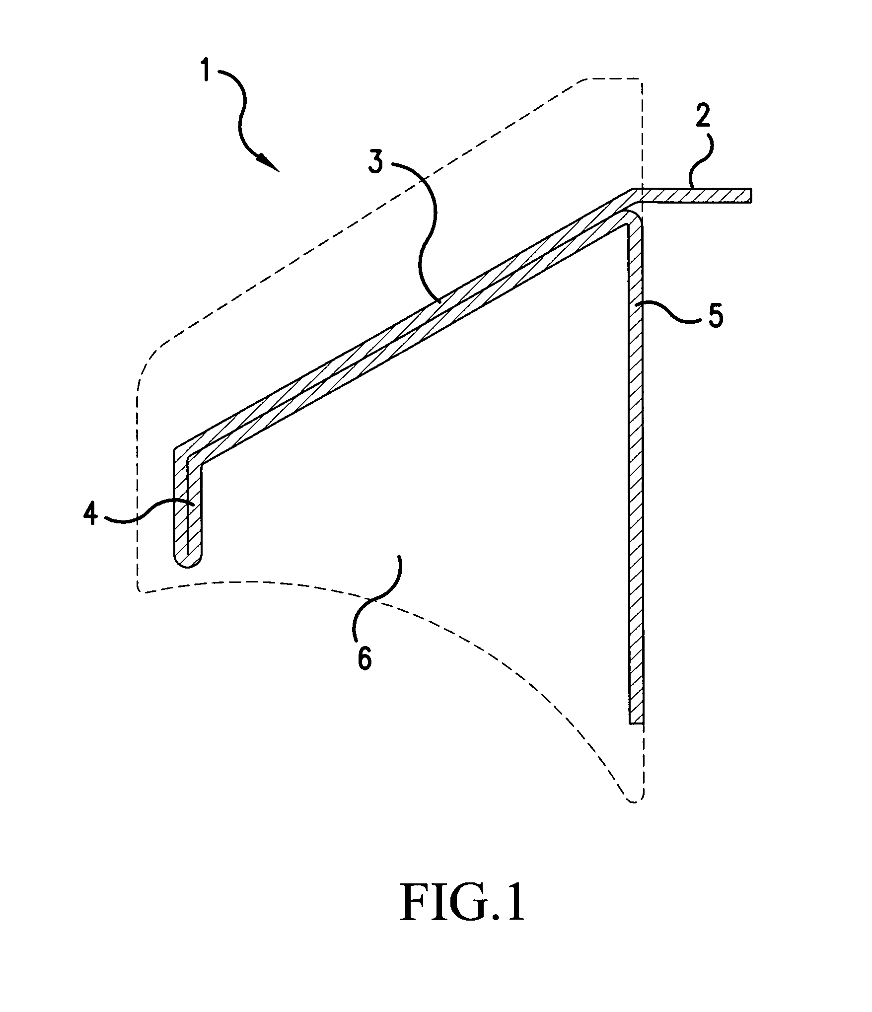
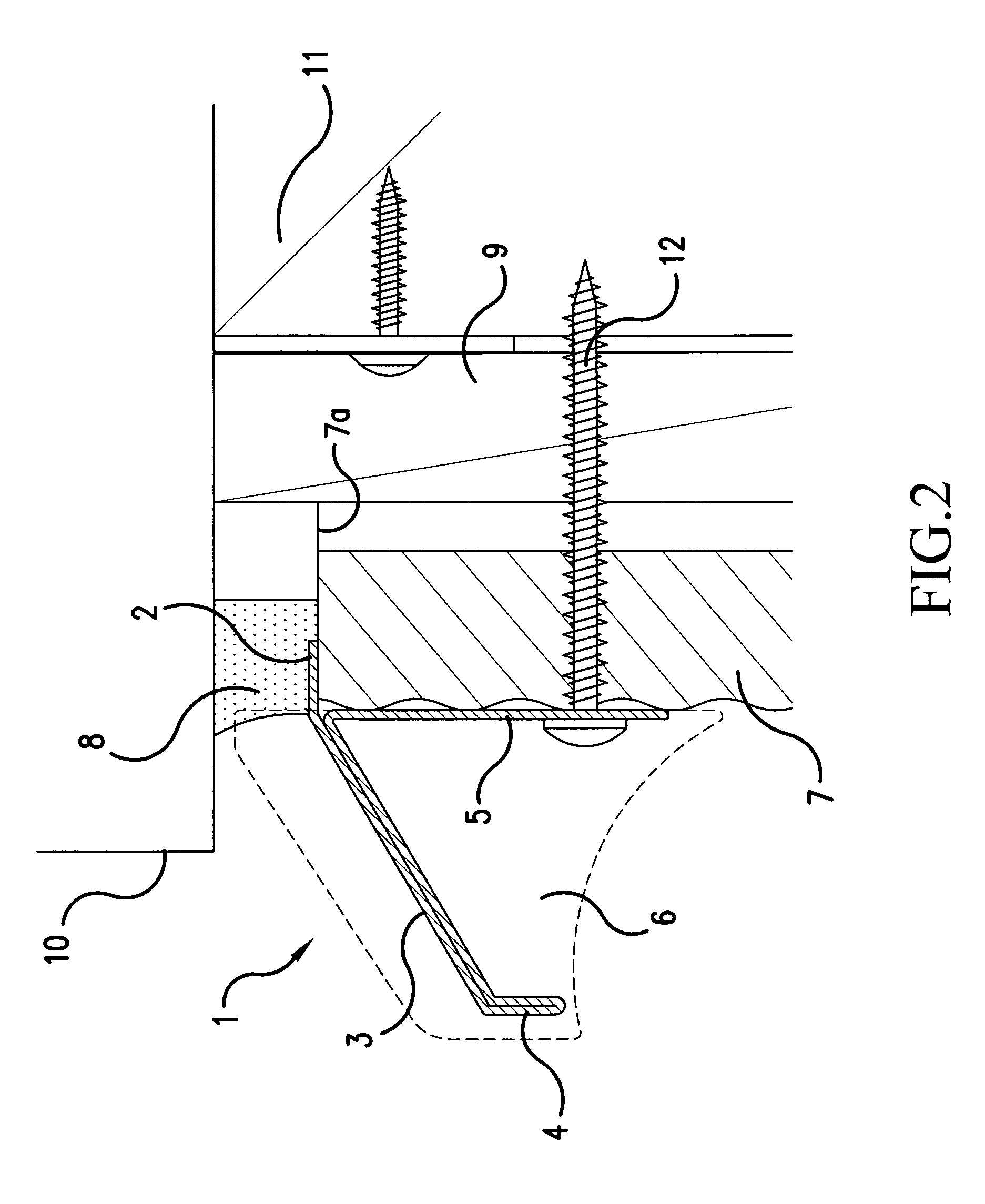
[0021]A window drain (1) having a horizontal portion for latching to an upper portion of an external wall (2), a sloping portion (3), a front portion (4), and a vertical portion (5), is shown in FIG. 1. As shown in FIG. 2, a sash window frame (10) is fixed to a building wall or a post (11), which is positioned underneath a sash window frame, with screws. Further, a furring strip (9) is installed as a support for an external wall (7) under the sash window frame (10). Further, the window drain (1) is temporarily held so that the horizontal portion touches an end (7a) of the external wall (7). Then, while keeping the vertical portion (5) touching the external wall (7), the position to be installed is adjusted and then is fixed to external wall (7) with screws (12). In FIG. 2, the portion described with a broken line is an end-cap (an upstanding portion) (6).

[0022]As...


PUM


Abstract

A window drain for preventing stains on a building wall and damage caused by (frozen) rain water, which is installable and sealable easily without impairing the appearance of a building. The present invention relates to a window drain adaptable to be positioned beneath a sill of a sash window frame having a vertical portion, a sloping portion, a front portion, and a horizontal portion for latching to an upper portion of an external wall. Further, the present invention relates to a window drain, wherein the horizontal portion has notches at both ends thereof. Further, the present invention relates to a window drain, further having upstanding portions at both ends of the window drain to regulate a stream of water so that the water is kept between the upstanding portions.

Description

[0001]This non-provisional application claims priority under 35 U.S.C. §119(a) on Japanese Patent Application No. JP2007-005039U, filed on Jul. 2, 2007, which is herein incorporated by reference.FIELD OF THE INVENTION[0002]The present invention relates to a window drain adapted to be positioned beneath a sash window frame of a building.BACKGROUND OF THE INVENTION[0003]A variety of structures of window drains are known in the art. For example, in the case where a window drain is installed underneath a sash window frame, a window drain having a vertical portion which is fixable to a wall and further wherein the vertical portion has holes (openings) for accepting a screw to fix the window drain is known. The hole extends downwardly and an end of the hole is open so that an adjustment in a vertical direction can be carried out easily. Further, a window drain may have a round concave portion so that sealing material can be filled into the space between an external wall and the window dra...

Claims


Application Information

Patent Timeline
Patent Type & Authority Patents(United States)
IPC IPC(8): E06B7/14E06B7/26
CPCE06B1/705E06B1/702
Inventor SAWADA, KOJI
Owner NICHIHA CORP
Learn More