Heat recovery ventilator with defrost

a ventilator and defrost technology, applied in the field of defrost systems, can solve the problems of heat energy loss, negative pressure on the interior space of the interior space, and prior art hrv systems that cannot solve,

Active Publication Date: 2011-05-17
NU AIR VENTILATION SYST
View PDF7 Cites 14 Cited by
  • Summary
  • Abstract
  • Description
  • Claims
  • Application Information

AI Technical Summary

Benefits of technology

[0020]a second damper having a first open position enabling exhaust air to pass through the exhaust air inlet port, and a second position preventing exhaust air from passing through the exhaust air inlet port;
[0021]a third damper having a first open position enabling exhaust air to pass through the exhaust air outlet port, and a second position preventing exhaust air from passing through the exhaust air outlet port;

Problems solved by technology

Unfortunately, prior art HRV systems do not, without drawbacks, solve the problem of heat exchange cores becoming too cold and frosting over.
Unfortunately, fan shut-down defrost systems cause negative pressurization of the interior space, as they exhaust air through the HRV / ERV core to thaw the core out, without introducing fresh air into the interior space because the fresh air fan is “shut down” during defrost cycles.
Moreover, during defrost cycles, fan shut-down HRV / ERV systems expel heat from the interior space without passing any of that heat on to incoming fresh air, since fresh air is not coming into the building when the fresh air fan is shut off, resulting in heat energy loss.
Another short-coming of fan shut-down defrost systems is that they take longer to defrost the HRV / ERV core than other defrost systems because fan shut-down systems provide warm air to only one side of the core.
There is no negative pressurization of the interior space and its associated heat energy loss, no need to locate or run special ductwork, nor any special consideration needed for unit location (in terms of defrost performance), all typical disadvantages of “5th port” defrost systems.
Conventional 5th port defrost systems address the issue of feeding defrost air to both sides of the HRV / ERV core, thereby performing their function faster than fan shut-down defrost systems; however, they still create negative pressurization of the interior space resulting in energy losses.
Another disadvantage of 5th port defrost systems is that they require an extra duct, which is used for defrost purposes, to be run between the unit and the interior space.
As the space in building design for mechanical ventilation systems is usually minimal, adding a 5th port can present major space and aesthetic issues, not to mention added costs of running the duct for the 5th port.
Re-circulation defrost systems address the efficiency, space, aesthetic and cost shortcomings of fan shut-down and 5th port defrost systems; however, recirculation defrost systems re-circulate stale and exhaust air through the HRV / ERV core, thus delivering, stale and perhaps smelly air to the interior space during defrost cycles, adversely affecting the level of comfort experienced by occupants of the interior space.

Method used


Image

  • Heat recovery ventilator with defrost
  • Heat recovery ventilator with defrost
  • Heat recovery ventilator with defrost

Examples


Embodiment Construction

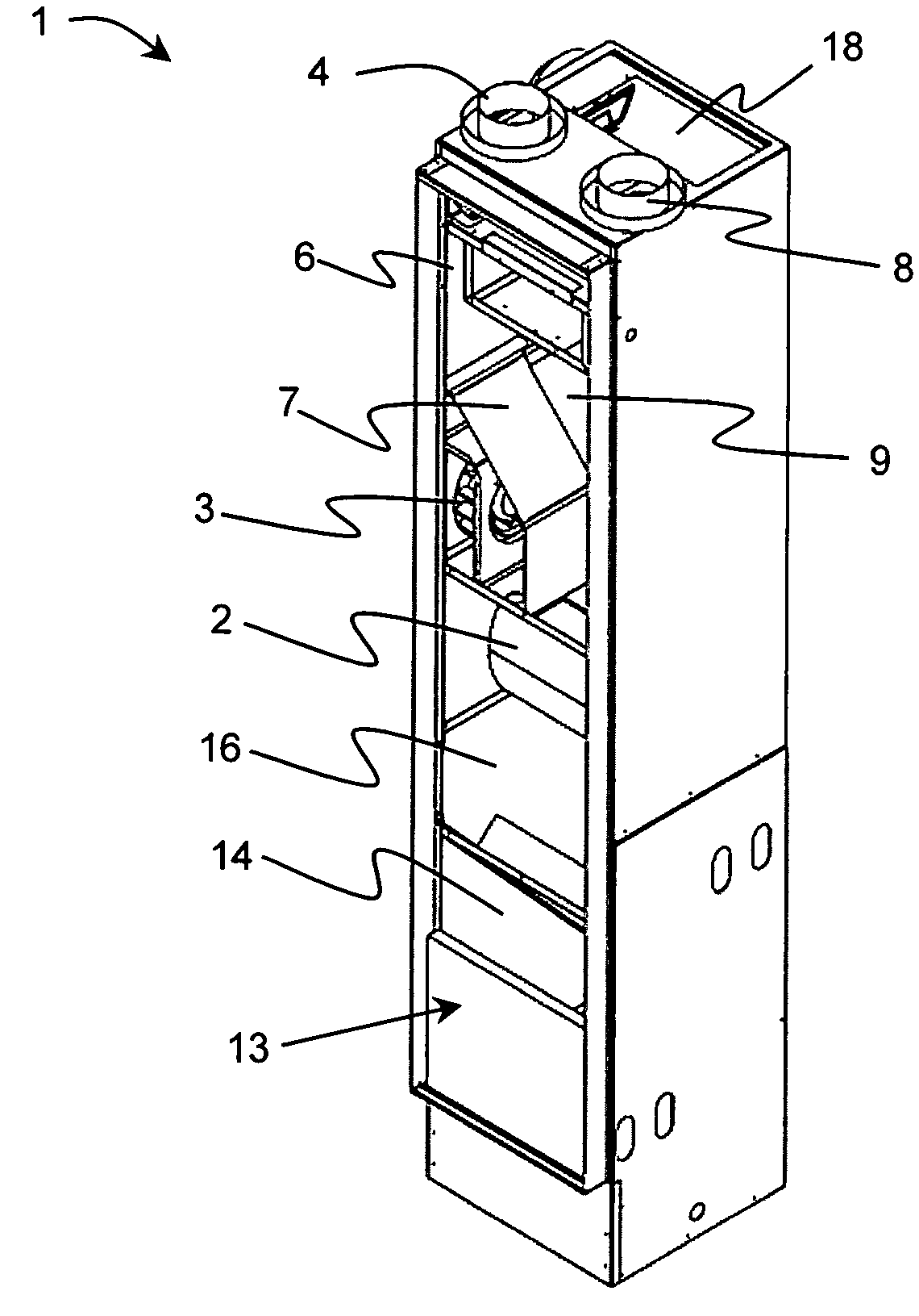
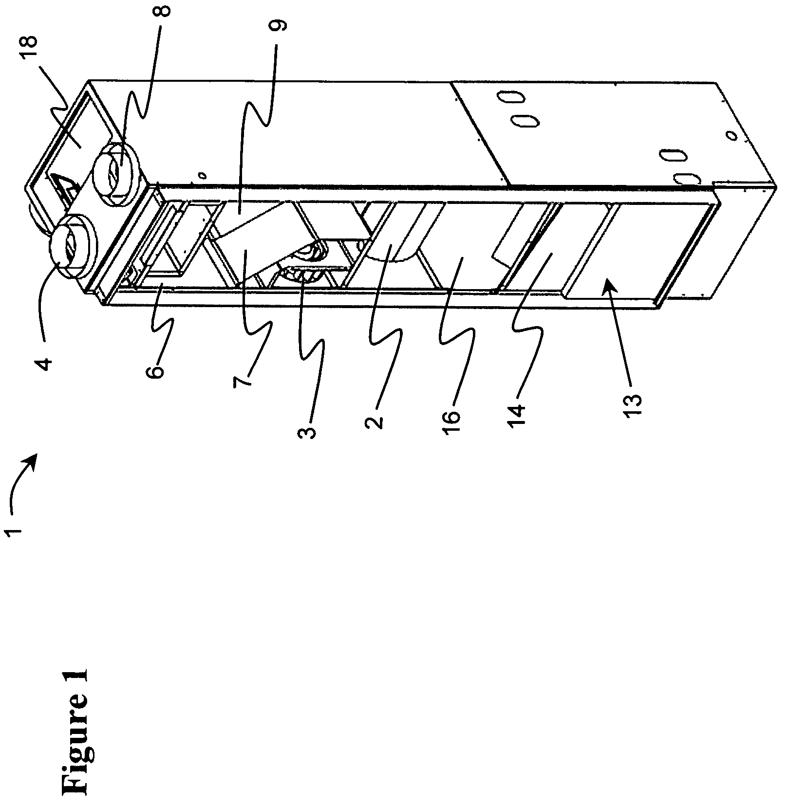
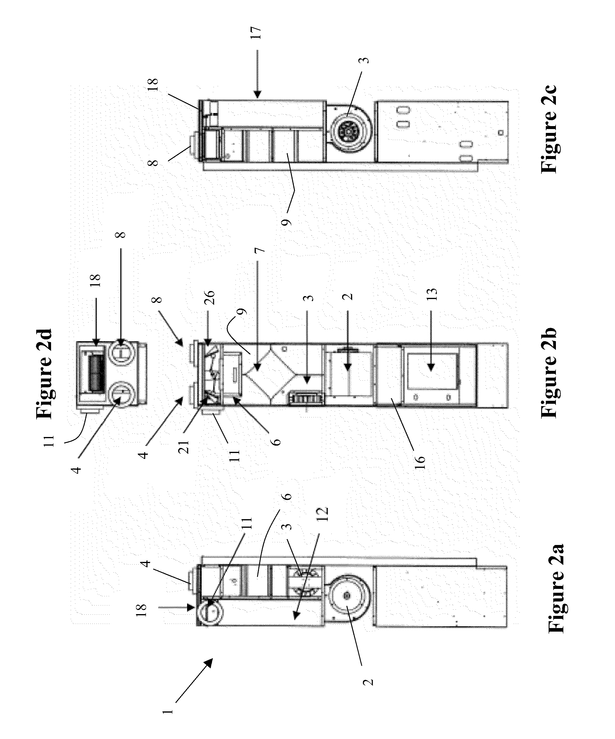
[0034]With reference to FIGS. 1 to 3c, the integrated fan coil of the present invention includes a generally rectangular housing 1 resting on one end, with a main fan 2 and a secondary fan 3 disposed proximate the middle thereof. During normal operation, the main fan 2 draws in fresh air from the outside, draws in return air only from a first group of selected rooms on the inside of the structure, and delivers supply air to all of the rooms on the inside of the structure. A secondary fan 3 is provided for drawing in exhaust air only from a second group of selected interior rooms for preheating the fresh outside air, as explained hereinafter, and delivering the exhaust air to the outside of the structure. Although this description refers to specific locations of air ports, it should be noted that the location of these ports may vary as building design dictates.

[0035]During normal operation, fresh outside air is drawn in by the main fan 2 through the fresh air intake port 4, at an upp...


PUM


Abstract

A defrost system for a heat recovery ventilator / energy recovery ventilator (HRV / ERV), uses the interior space supply air of an integrated fan coil for defrosting a HRV / ERV core without creating negative pressure in the interior space, which wastes energy, without need of an external fifth port from which to draw defrost air from the interior space, which increases costs, and without re-circulating exhaust air into the interior space. During the defrost cycle, automatically controlled dampers close off the fresh air and exhaust air inputs, and exhaust output, and circulate supply air through the heat exchange core and into to the living space.

Description

CROSS-REFERENCE TO RELATED APPLICATIONS[0001]The present invention claims priority from U.S. Patent Application No. 60 / 996,522 filed Nov. 21, 2007, by Caldwell, entitled “INTEGRATED FAN COIL SUPPLY AIR DEFROST METHOD”, which is incorporated herein by reference for all purposes.TECHNICAL FIELD[0002]The present invention relates to a defrost system for a heat recovery ventilator / energy recovery ventilator (HRV / ERV), and in particular to a defrost system that utilizes interior space supply air to defrost the core in the integrated fan coil of the HRV / ERV.BACKGROUND OF THE INVENTION[0003]An integrated fan coil refers to an air handling system which combines in one appliance the typical functions of a hydronic or direct exchange air handler and the typical functions of an HRV / ERV device. A typical direct exchange air handler includes a forced air furnace circulating heated or air conditioned air to an interior space via a duct or direct grille return system. A typical HRV or ERV device b...

Claims


Application Information

Patent Timeline
Patent Type & Authority Patents(United States)
IPC IPC(8): A23C3/02F24H3/02F24F7/00
CPCF24F12/006Y02B30/563F24F2011/0087F24F11/41Y02B30/56
Inventor CALDWELL, BRADLEY D.
Owner NU AIR VENTILATION SYST
Why Eureka
Try Eureka