Magnetic field forming device for active water and fluid treatment apparatus using the same

a technology of active water and forming device, which is applied in the direction of magnetic separation, separation process, filtration separation, etc., can solve the problems of uneven activation degree of water based on magnets, workers assembling apparatus, and apparatus whose activation efficiency is very low, etc., to achieve excellent assembling efficiency, high magnetic field, and excellent stability

Active Publication Date: 2011-05-17
TOKO KABUSHIKI KAISHA
View PDF22 Cites 3 Cited by
  • Summary
  • Abstract
  • Description
  • Claims
  • Application Information

AI Technical Summary

Benefits of technology

As described above, according to the magnetic field forming device for active water and the fluid treatment apparatus using the same, the following effects may be brought about.
(1) a fluid such as water is brought from the communication portion into a fluid flow path formed between the inner wall of the through hole and the side of a magnet, and a high magnetic field that is uniform is formed in the fluid flow path by a magnetic force of a magnet disposed one by one in each of the through holes. Therefore, it is possible to provide a magnetic field forming device for active water, having excellent stability, by which the fluid may be securely activated.
(2) since a fluid is activated by the magnetic force of magnets disposed one by one in each of the through holes regardless of the orientation of magnetic polarity of the magnets, assembling efficiency thereof is excellent because it is not necessary to assemble while checking the orientation of the magnets, and may be manufactured at a high product yield ratio without occurrence of defective products resulting from a difference in the orientation of magnets.
(3) it is possible to provide a magnetic field forming device for active water, being excellent in assembling efficiency, where a magnet is disposed in a through hole, the magnet may be inserted with predetermined spacing to the through hole by causing the guide member to slide without the magnet magnetically adhered to the inner wall of the through hole by inserting the guide member, which is adhered to and fixed to the magnet, through one opening portion of the through hole and manually pushing the opposite side of the guide member.
(4) it is possible to provide a magnetic field forming device for active water, being excellent in maintenance efficiency, for which, where a magnet is taken out from the through hole, the magnet having the guide member adhered and fixed thereon may be easily pushed out from the through hole without use of any exclusive special tool by causing the magnet to slip by inserting and pushing a rod material through one opening portion of the through hole. After the magnets are pushed out, rust and stains adhered to the magnets may be wiped off one by one.
(5) when disposing a magnet by pushing a guide member into a through hole, since the guide member is provided with an inclined portion the diameter of which is reduced toward the magnet, the inclined portion is slidingly brought into contact with the edge of the opening portion of the through hole and guides the guide member when pushing the guide member into the opening portion. Therefore, it is possible to provide a magnetic field forming device for active water, having excellent work efficiency, which is capable of smoothly inserting the guide member in the opening portion and disposing the magnet into the interior of the through hole.

Problems solved by technology

However, there are the following problems in the prior art.
Therefore, it is necessary that the magnets are disposed with predetermined orientations when assembling the apparatus, wherein it becomes cumbersome to assemble the apparatus while checking the orientation of the magnets, and since the polarity of the magnets are not visible, there is a possibility for a worker to assemble the apparatus with a difference in the orientation of the magnets.
As such, there is a problem in that since water flowing between magnets opposed to each other with the same polarity is not activated, an apparatus whose activation efficiency is very low is produced without notice.
(2) With respect to the section of the water flowing channel in the direction orthogonal to the flow of a fluid, the magnetic force will become weaker and weaker in line with moving away from the magnets, and unevenness is brought about in the intensity of the magnetic field, wherein there is a problem that the activation degree of water based on the magnets becomes uneven.
Therefore, where one-time passed water that passes through a water activation apparatus only once is activated, there is a problem that the activation degree of water is lowered.

Method used


Image

  • Magnetic field forming device for active water and fluid treatment apparatus using the same
  • Magnetic field forming device for active water and fluid treatment apparatus using the same
  • Magnetic field forming device for active water and fluid treatment apparatus using the same

Examples


embodiment 1

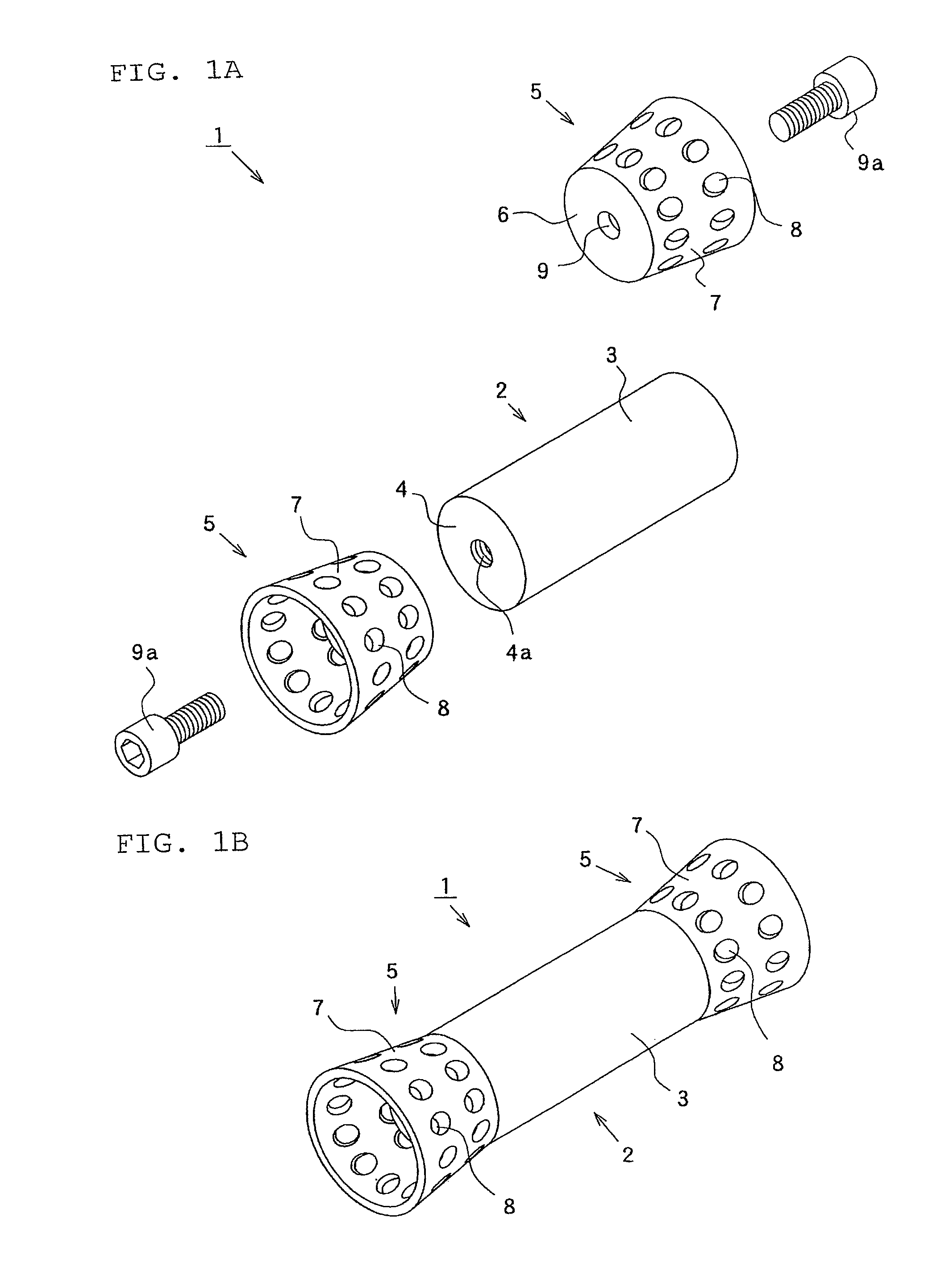
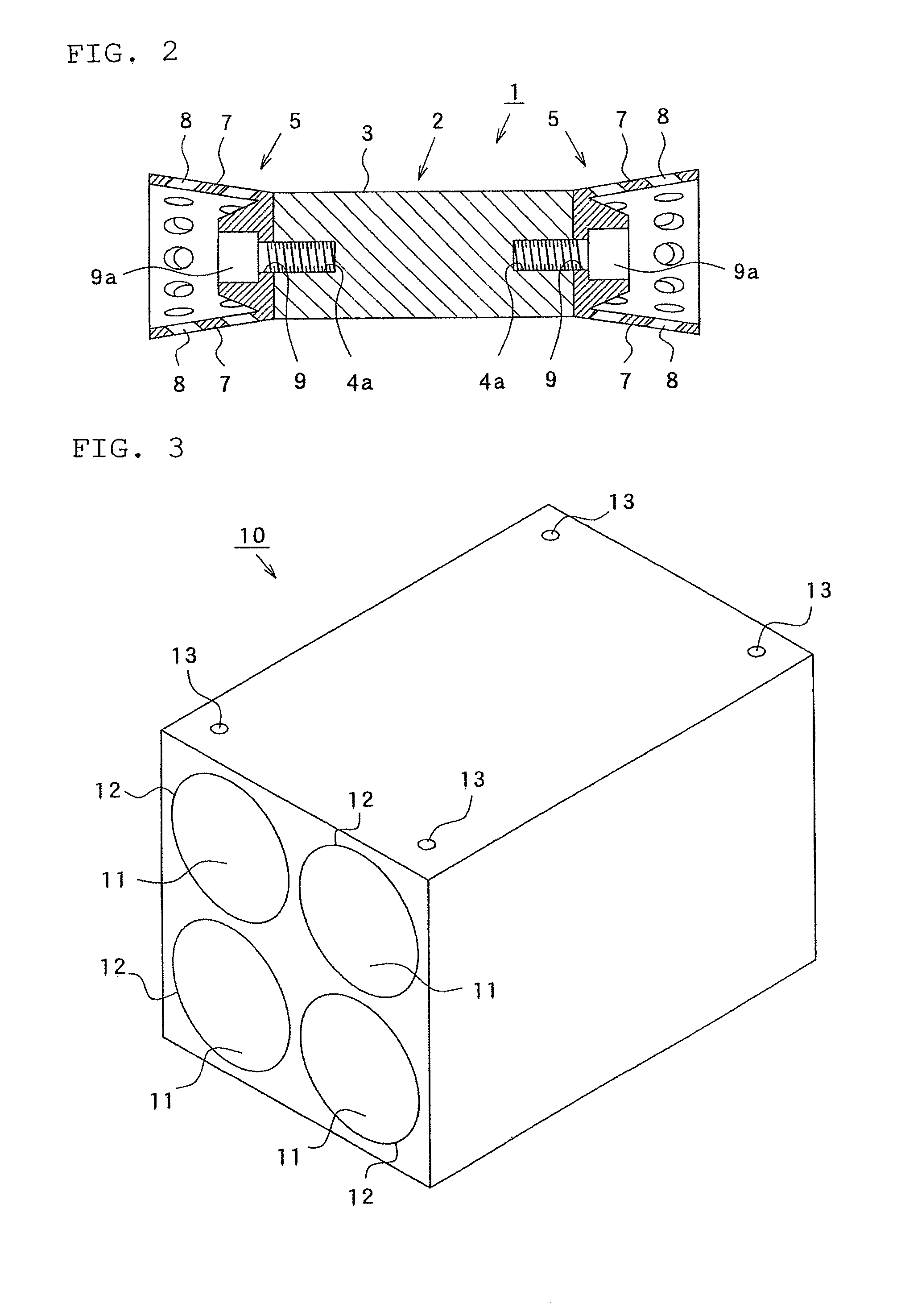
FIG. 1A is a disassembled perspective view showing a magnetic field forming device for active water according to Embodiment 1 of the present invention, FIG. 1B is a perspective view showing the magnetic field forming device for active water, and FIG. 2 is a sectional view showing the major parts of the magnetic field forming device for active water.

In FIG. 1 and FIG. 2, reference numeral 1 denotes a magnetic field forming device for active water according to Embodiment 1 of the present invention, 2 denotes a magnet formed of rare earth Cobalt magnet etc., formed to be like a round bar, 3 denotes the side of the magnet 2, 4 denotes an end side of the magnet 2, 4a denotes a threaded hole portion formed at the end side 4 of the magnet 2, 5 denotes a guide member that is formed of a non-magnetizable material such as aluminum alloy, copper alloy, titanium alloy, Inconel, stainless steel, high manganese steel, synthetic resin, and inorganic material, etc., and is adhered to and fixed to t...

embodiment 2

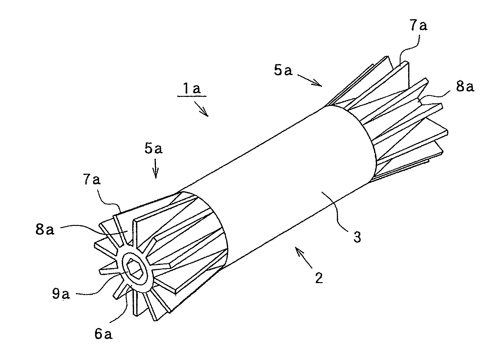
FIG. 8 is a perspective view showing a magnetic field forming device for active water according to Embodiment 2, FIG. 9A is a perspective view observed from the inclined portion side of a guide member of a magnetic field forming device for active water according to a modified version of Embodiment 2, and FIG. 9B is a perspective view observed from the base portion side. Also, parts that are similar to those described in Embodiment 1 are given the same reference numerals, and the description thereof is omitted.

In FIG. 8, reference numeral 1a denotes a magnetic field forming device for active water according to Embodiment 2 of the present invention, 2 denotes a magnet, 3 denotes the side of the magnet 2, 5a denotes a guide member formed of a non-magnetizable material such as aluminum alloy, copper alloy, titanium alloy, Inconel, stainless steel, high manganese steel, synthetic resin, inorganic material, etc., 6a denotes a base portion formed to be cylindrical, the end portion of which...

embodiment 3

FIG. 10 is a sectional view showing the major parts of a fluid treatment apparatus according to Embodiment 3 of the present invention, and FIG. 11 is a sectional view showing the major parts of a fluid treatment apparatus according to a modified version of Embodiment 3. Also, parts that are similar to those described in Embodiment 1 are given the same reference numerals, and the description thereof is omitted.

In FIG. 10, reference numeral 41 denotes a fluid treatment apparatus according to Embodiment 3, 42 denotes a treatment chamber of the fluid treatment apparatus 41, which is formed of a light material almost free from corrosion such as titanium alloy, Inconel, stainless steel, high manganese steel, synthetic resin, inorganic material, etc., to be like a rectangular parallelepiped box having a bottom with its upper surface open, and in which casings 10 having four magnets 2 accommodated at the bottom thereof are juxtaposed by two lines, 43 denotes a casing in which two magnets 2 ...


PUM

PropertyMeasurementUnit
outer diameteraaaaaaaaaa
magneticaaaaaaaaaa

Abstract

An object of the present invention is to provide a magnetic field forming device for active water capable of uniformly forming a high magnetic field free from any unevenness in its intensity, activating a fluid regardless of the orientation of magnetic polarity of the magnets, bringing about excellent assembling efficiency not requiring assembling while checking the orientation of the magnets, being manufactured at a high product yield ratio without occurrence of defective products resulting from a difference in the orientation of the magnets, remarkably easily taking out the magnets without use of any exclusive special tool, and removing rust and stains adhered to the magnets by wiping off the magnets one by one, the maintenance efficiency of which is excellent. The magnetic field forming device for active water in which a flow path of a fluid is formed in a through hole, and the same magnetic field forming device includes a rod-shaped magnet 2 disposed with predetermined spacing from the inner wall of the through hole and having a fluid flow path formed between the inner wall and the side 3; a guide member 5 adhered to and fixed to the end part of the magnet 2, which is inserted into the interior of the through hole; and a communication portion 8 formed at the guide member 5, which communicates with the fluid flow path.

Description

CROSS REFERENCE TO RELATED APPLICATIONThis application is a National Stage of International Application No. PCT / JP2008 / 050500 filed Jan. 17, 2008, claiming priority based on Japanese Patent Application No. 2007-120164, filed Apr. 27, 2007, the contents of all of which are incorporated herein by reference in their entirety.TECHNICAL FIELDThe present invention relates to a magnetic field forming device for active water, which activates a fluid by causing the fluid to pass through a magnetic field, and fluid treatment apparatus using the same.BACKGROUND OF THE INVENTIONA fluid treatment apparatus has conventionally been known, which magnetically treats a fluid flowing in a piping by disposing a rod-shaped permanent magnet in the piping.As a prior art in such a fluid treatment apparatus, Patent Document 1 discloses “a water activating apparatus that magnetically treats and activates water flowing between the sides of opposed magnets (water flowing channel) by disposing the magnets with ...

Claims


Application Information

Patent Timeline
Patent Type & Authority Patents(United States)
IPC IPC(8): B01D35/06B03C1/00C02F1/48
CPCC02F1/006C02F1/481C02F2303/14C02F1/48C02F2201/48
Inventor YAMASAKI, JUNICHI
Owner TOKO KABUSHIKI KAISHA
Why Eureka
Try Eureka