Method for determining adequacy of seismic data coverage of a subsurface area being surveyed and its application to selecting sensor array geometry

a technology of seismic data and subsurface area, applied in the field of seismic surveying of the earths subsurface, can solve the problems of obscuring the geologic picture, amplitude distortion, particularly troublesome,

Inactive Publication Date: 2011-05-17
APACHE CORPORATION
View PDF16 Cites 26 Cited by
  • Summary
  • Abstract
  • Description
  • Claims
  • Application Information

AI Technical Summary

Problems solved by technology

Amplitude distortions resulting from irregular distribution of source and receiver positions during data acquisition is a particularly troublesome non-geologic effect.
If uncorrected, these non-geologic effects can distort the seismic image and obscure the geologic picture.
In practice, there are typically irregularities in the distribution of sources and receivers.
Such artifacts can interfere with the interpretation of the seismic image and attribute maps.
In marine seismic streamer surveys, if data density criteria known in the art are used, portions of the subsurface may be believed to be inadequately covered with seismic data recordings due to streamer feathering and other causes.
These additional passes significantly increase the time and associated cost to complete a survey.
There are several problems with such procedure.
This is often referred to as “bin smear”, and results in the loss of high frequency data content for dipping reflective events.

Method used


Image

  • Method for determining adequacy of seismic data coverage of a subsurface area being surveyed and its application to selecting sensor array geometry
  • Method for determining adequacy of seismic data coverage of a subsurface area being surveyed and its application to selecting sensor array geometry
  • Method for determining adequacy of seismic data coverage of a subsurface area being surveyed and its application to selecting sensor array geometry

Examples


Embodiment Construction

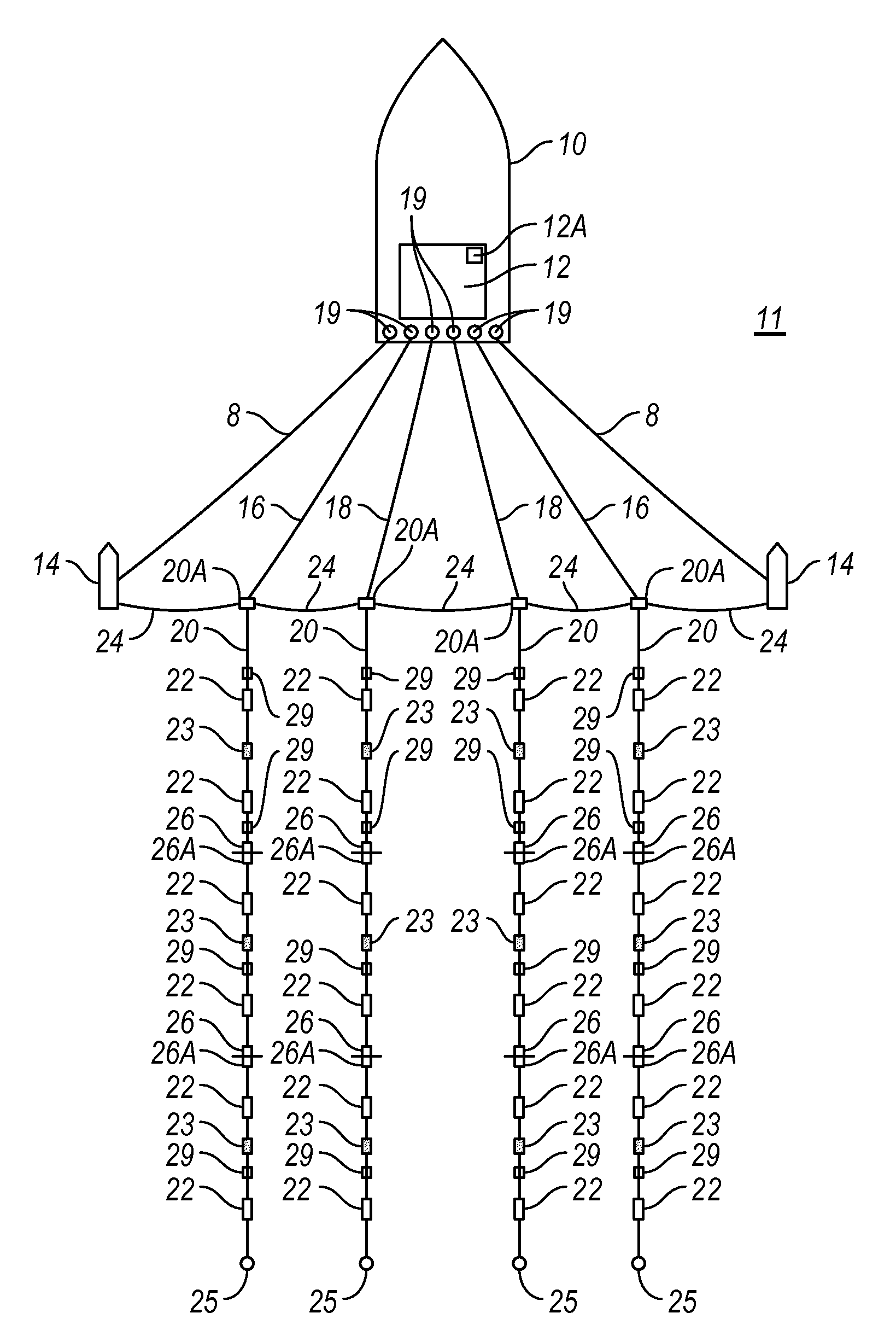
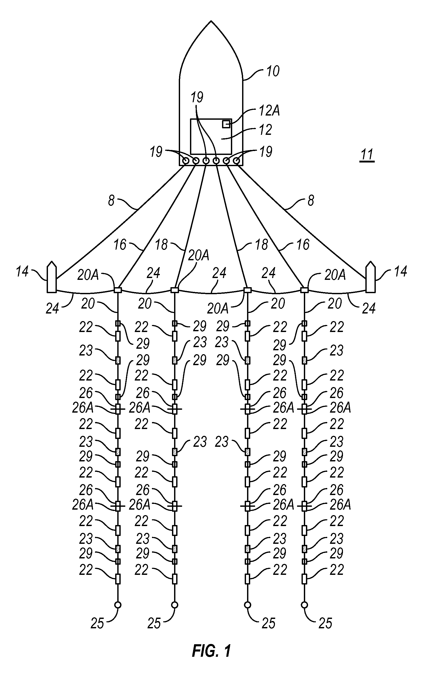
[0032]FIG. 1 shows a typical marine seismic survey system that can be used with various aspects of the present invention. The seismic survey system can include a survey vessel 10 that moves along the surface of a body of water 11 such as a lake or the ocean. The survey vessel 10 may include thereon electronic equipment, shown generally at 12 and for convenience collectively referred to as a “recording system.” The recording system 12 typically includes devices such as a data recording unit (not shown separately) for making a record with respect to time of signals generated by various sensors in the acquisition system. The recording system 12 also typically includes navigation equipment (not shown separately) to determine and record, at selected times, the geodetic position of the vessel 10, and using other devices to be explained below, each of a plurality of seismic sensors 22 disposed at spaced apart locations on streamers 20 towed by the survey vessel 10.

[0033]A device for determ...


PUM


Abstract

A method for marine seismic surveying includes towing seismic sensors in a plurality of streamers in the water, actuating a seismic energy source in the water at selected times and detecting seismic signals at the sensors resulting from the actuation of the source. A data trace is created for each of the detected signals. At least one Fresnel zone is determined for at least some of the seismic data traces. A contribution of each of the traces to each one of a plurality of bins defined in a predetermined pattern is computed, based on the Fresnel zone associated with each trace. Based on the computed contributions, a maximum lateral distance between corresponding seismic sensors is determined that will result in a contribution sum above a selected threshold.

Description

CROSS-REFERENCE TO RELATED APPLICATIONS[0001]Continuation in part of U.S. patent application Ser. No. 12 / 116,373 filed on May 7, 2008.STATEMENT REGARDING FEDERALLY SPONSORED RESEARCH OR DEVELOPMENT[0002]Not applicable.BACKGROUND OF THE INVENTION[0003]1. Field of the Invention[0004]The invention relates generally to the field of seismic surveying of the Earth's subsurface. More specifically, the invention relates to methods for determining whether seismic data have been acquired to sufficient spatial density to avoid distortions in generating images of the Earth's subsurface from seismic data.[0005]2. Background Art[0006]In seismic surveying, seismic energy sources are used to generate a seismic signal that propagates into the earth and is at least partially reflected by subsurface seismic reflectors. Such seismic reflectors typically are located at the interfaces between subterranean formations having different acoustic properties, specifically differences in acoustic impedance at t...

Claims


Application Information

Patent Timeline
Patent Type & Authority Patents(United States)
IPC IPC(8): G01V1/20G01V1/28
CPCG01V1/3808
Inventor MONK, DAVIDYOUNG, PAUL G
Owner APACHE CORPORATION
Why Eureka
Try Eureka