

Mounting of fiber optic cable assemblies within fiber optic shelf assemblies
a technology of fiber optic cables and shelf assemblies, applied in the direction of optics, optical light guides, instruments, etc., can solve the problems of cumbersome detachment of installed furcation assemblies and reattaching them to fiber optic equipment, inability to easily integrate securing techniques into fiber optic equipment and/or not securely mount, and inability to achieve high-density fiber optic equipment designs
- Summary
- Abstract
- Description
- Claims
- Application Information
AI Technical Summary
Benefits of technology
Problems solved by technology
Method used
Image

Examples
Embodiment Construction
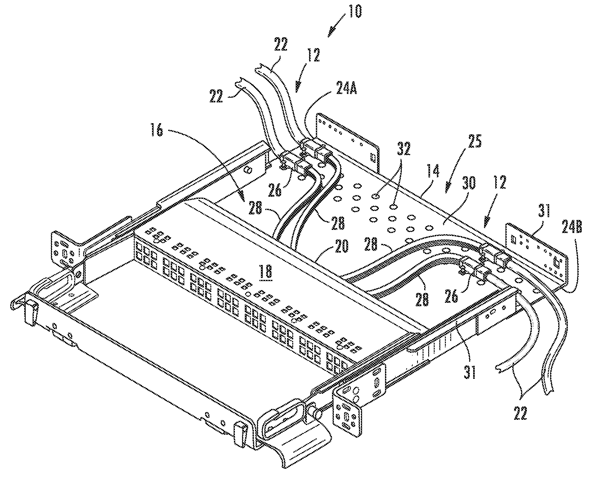
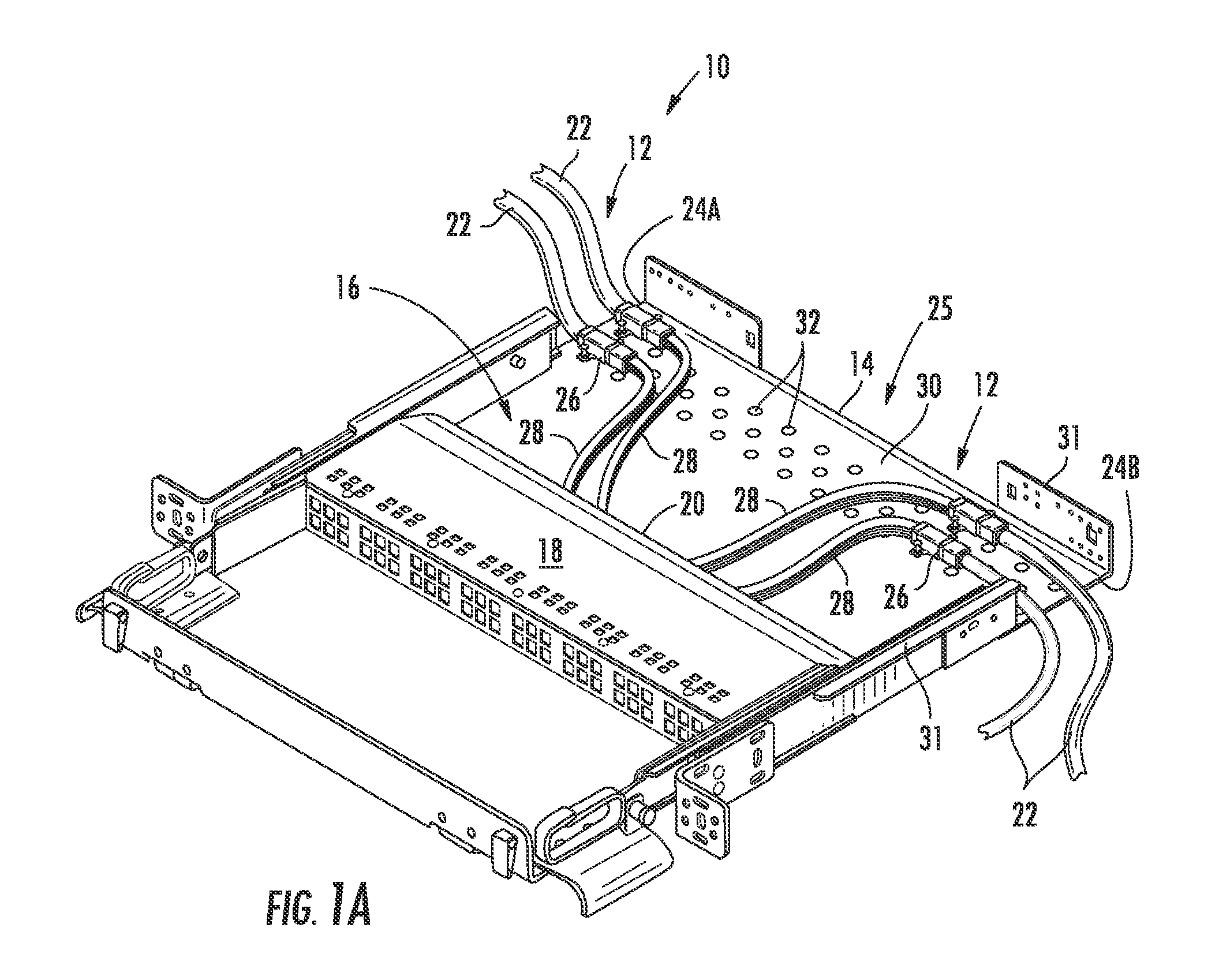
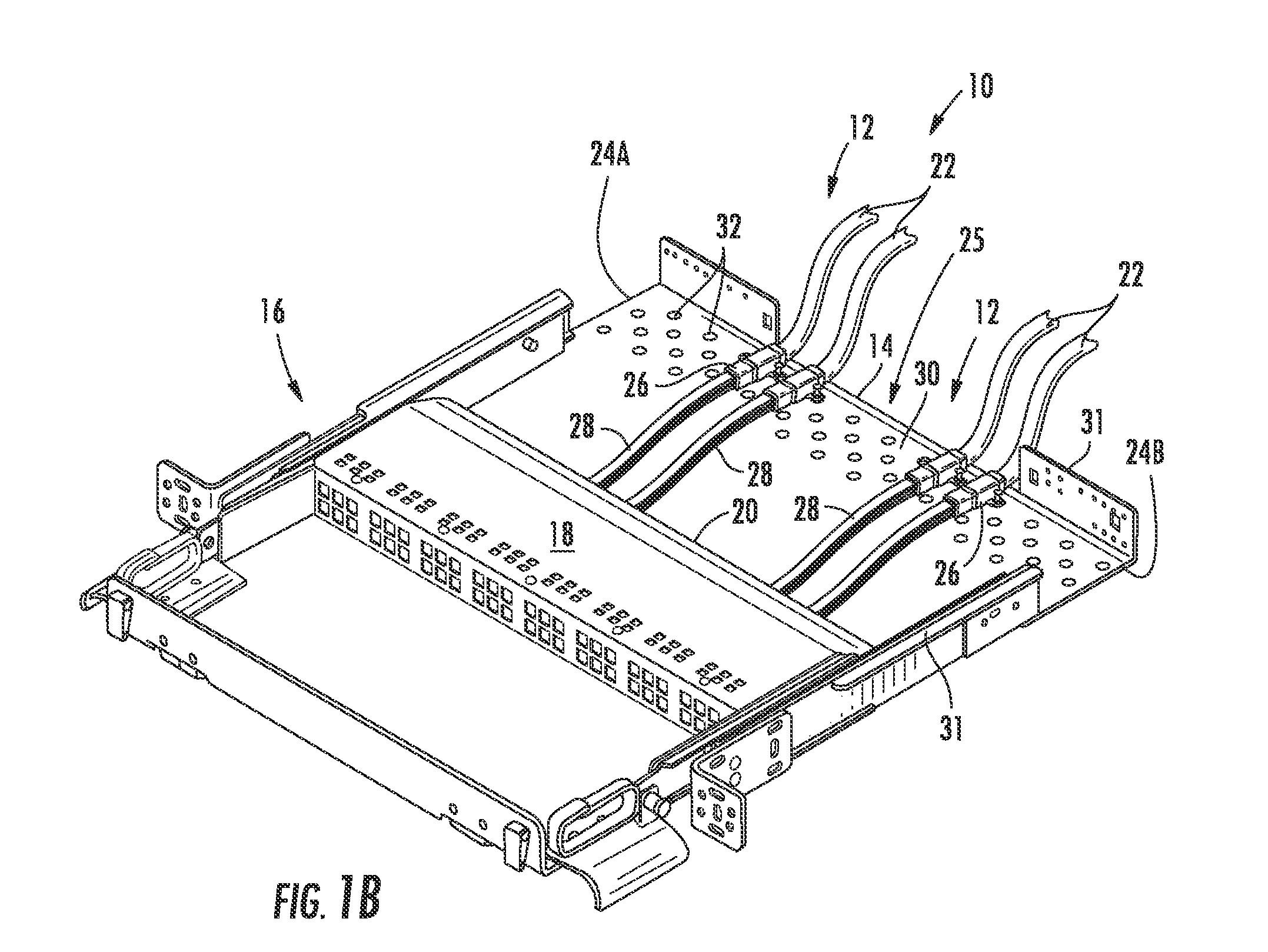
[0008]Disclosed are fiber optic shelf assemblies and furcation mounting structures for securing a plurality of furcation bodies of respective fiber optic cable assembles within the fiber optic shelf In one embodiment, the fiber optic shelf has a one-to-one correspondence between a plurality of respective modules and the respective fiber optic cable assemblies. By way of example, twelve furcation bodies of twelve respective fiber optic cable assemblies are secured within the fiber optic shelf and each fiber optic cable assembly is connected to a respective module. The concepts disclosed allow for securing relatively large numbers of furcation bodies within the fiber optic shelf assembly while advantageously allowing easy access, organization, and port mapping for the craft.
[0009]It is to be understood that both the foregoing general description and the following detailed description present embodiments of the invention, and are intended to provide an overview or framework for underst...
PUM
 Abstract
Description
Claims
Application Information