Torsion beam type rear wheel suspension system

a rear wheel and suspension system technology, applied in resilient suspensions, interconnection systems, vehicle springs, etc., can solve problems such as lateral shifting of stabilizer bush, and achieve the effect of reducing the pressure that acts upon the stabilizer bush when water is splashed onto the stabilizer bush and minimizing the possibility

Inactive Publication Date: 2011-05-24
HONDA MOTOR CO LTD
View PDF20 Cites 7 Cited by
  • Summary
  • Abstract
  • Description
  • Claims
  • Application Information

AI Technical Summary

Benefits of technology

In view of such problems of the prior art, a primary object of the present invention is to provide a torsion beam type rear wheel suspension system including a stabilizer passed inside a hollow interior of a torsion beam and a stabilizer bush received inside the holler interior of the torsion beam to resiliently retain the stabilizer to the torsion beam which can effectively prevent the lateral shifting of the stabilizer bush during use.
A second object of the present invention is to provide a torsion beam type rear wheel suspension system which can effectively retain the stabilizer bush against lateral shifting without complicating the structure of the suspension system or adding to the manufacturing cost.
Thus, the vertical walls of the bracket effectively prevents the lateral shifting of the stabilizer bush, but no part of the bracket or stabilizer bush restrains the torsional deformation of the stabilizer or torsion beam. The vertical walls may be spaced apart from the stabilizer bush. Also, the structure is not costly and does not cause any complication or difficulty in the assembly work of the rear wheel suspension system.
If the stabilizer bush is formed with at least one through hole extending across a width thereof, the pressure that acts upon the stabilizer bush when water is splashed onto the stabilizer bush is reduced, and this also minimizes the possibility of the stabilizer bush being shifted or dislodged from the designated position.

Problems solved by technology

However, it was found that the stabilizer bush may shift laterally in position during use, and that the pressure of water that is splashed onto the stabilizer bush often causes such a lateral shifting of the stabilizer bush.

Method used


Image

  • Torsion beam type rear wheel suspension system
  • Torsion beam type rear wheel suspension system
  • Torsion beam type rear wheel suspension system

Examples


Embodiment Construction

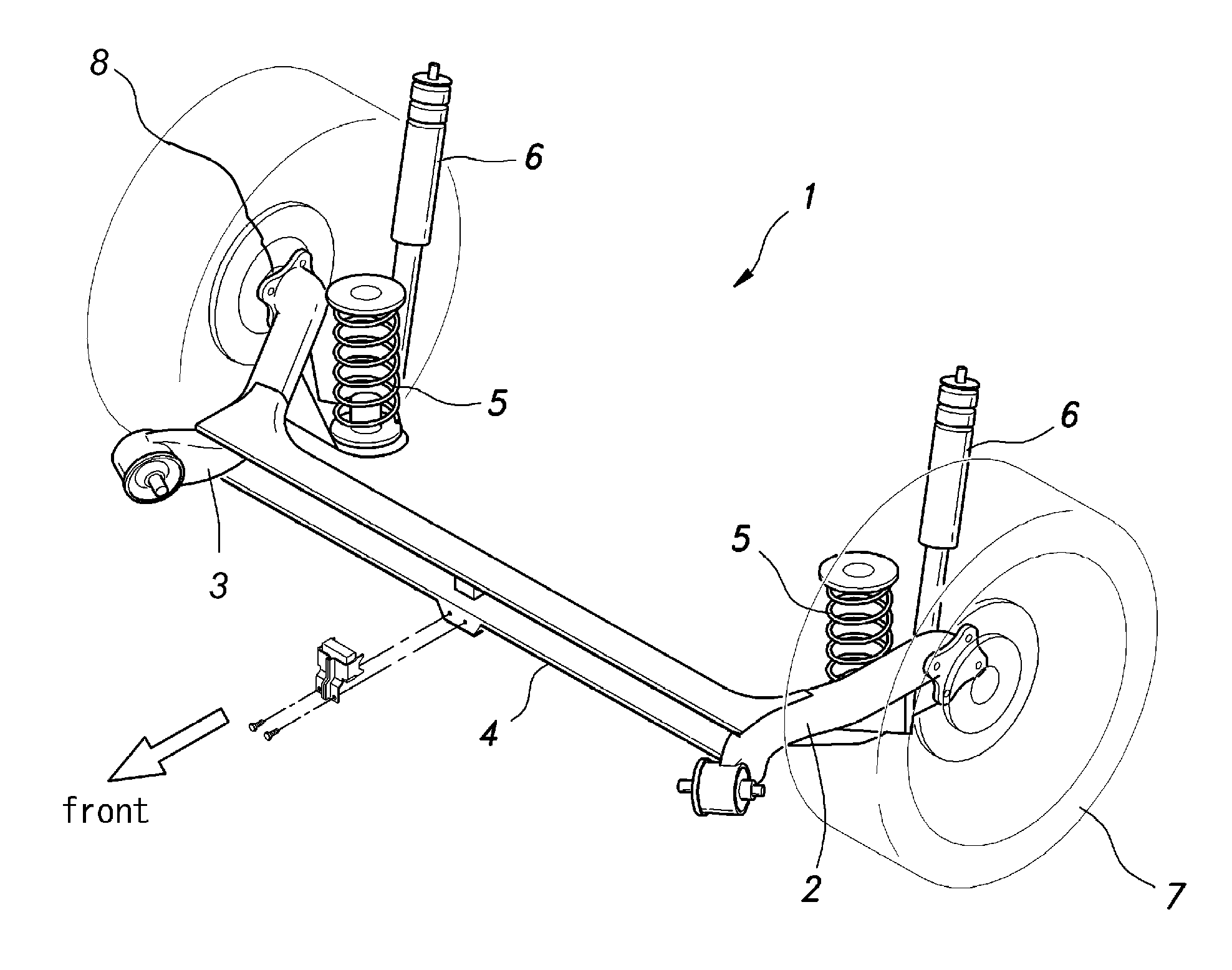
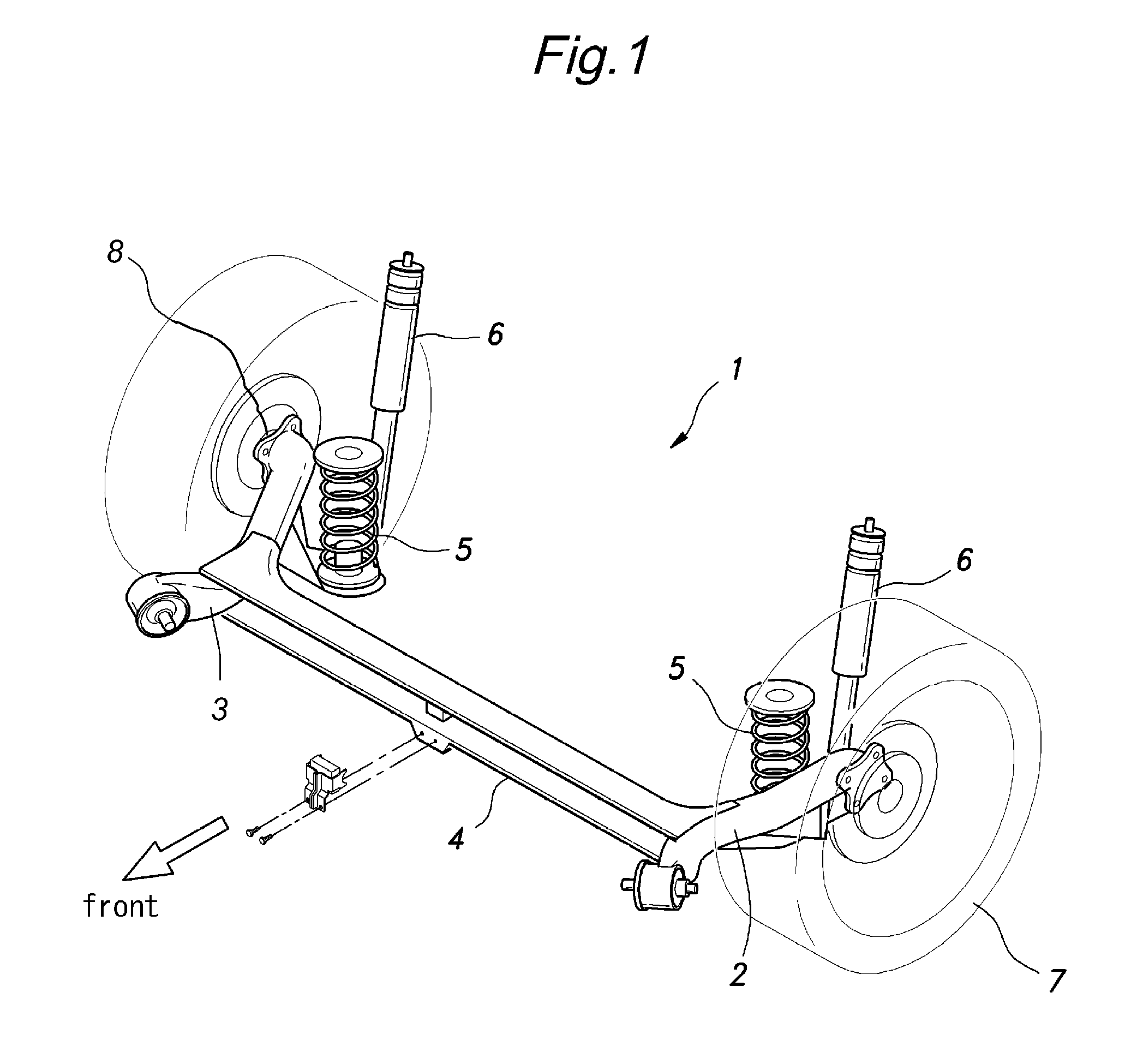
FIG. 1 shows a rear wheel suspension system of a passenger vehicle V. In the illustrated embodiment, the rear wheels 7 are supported by a H-type torsion beam wheel suspension system 1. The rear wheel suspension system 1 comprises a pair of trailing arms 2 each having a base end pivotally supported by a vehicle body 1 via a rubber bush joint 3 for a vertical swinging movement. Each trailing arm 2 curves outward as it extends rearward, and carries the corresponding rear wheel 7 via a hub bearing unit 8. Intermediate points of the trailing arms 2 are connected to each other by a torsion beam 4 extending laterally across the vehicle body. Each trailing arm 2 is provided with a spring seat at a point intermediate between the torsion beam 4 and the hub bearing unit 8, so that the trailing arm 2 may be resiliently supported by a coil spring 5 interposed between the spring seat and the opposing part of the vehicle body. Immediately behind the coil spring 5 is interposed a shock absorber 6, ...


PUM


Abstract

In a torsion beam wheel suspension system, a stabilizer bush made of resilient material is received in a hollow interior of a torsion beam that connect intermediate points of a pair of trailing arms, and retains an intermediate part of the stabilizer to the torsion beam. A bracket including a pair of vertical walls opposing lateral sides of the stabilizer bush is attached to a part of the torsion beam to prevent the lateral shifting of the stabilizer bush without any part of the bracket or stabilizer bush restraining the torsional deformation of the stabilizer or torsion beam. The vertical walls may be spaced apart from the stabilizer bush. The structure is not costly and does not cause any complication or difficulty in the assembly work of the rear wheel suspension system. The bracket may have dual purposes of retaining the stabilizer bush and supporting a dynamic damper.

Description

TECHNICAL FIELDThe present invention relates to a torsion beam type rear wheel suspension system including a torsion beam having a U-shaped cross section and a stabilizer received in a hollow interior of the torsion beam.BACKGROUND OF THE INVENTIONThe torsion beam type rear wheel suspension system is known as a preferred wheel suspension system for small passenger vehicles because of the favorable handling of the vehicle and the space saving which this wheel suspension system provides in spite of its highly simple structure. A torsion beam type rear wheel suspension system comprises a pair of trailing arms each having a front end pivotally supported by a vehicle body for a vertical swinging movement and a rear end extending rearwardly from the front end thereof and carrying a rear wheel rotatably supported thereby, a torsion beam extending between intermediate points of the trailing arms laterally across the vehicle body and having a U-shaped cross section and a stabilizer received ...

Claims


Application Information

Patent Timeline
Patent Type & Authority Patents(United States)
IPC IPC(8): B60G11/28B60G11/20B60G11/32
CPCB60G13/16B60G21/051B60G2204/122B60G2202/25B60G2202/1362
Inventor KOBAYASHI, AKIRA
Owner HONDA MOTOR CO LTD
Why Eureka
Try Eureka